[0024] Embodiments of the present invention will be described in detail below, and examples of the embodiments are illustrated in the drawings, in which the same or similar reference numerals represent the same or similar elements or elements having the same or similar functions. The following is exemplary, and is intended to be illustrative of the invention, not to be construed as limiting the invention.
[0025] In the description of the present invention, it is to be understood that the orientation or positional relationship of the orientation, such as upper, lower, prior,,, left, right, etc., based on the orientation or positional relationship shown in the drawings, is only In order to facilitate the description of the invention and simplified description, rather than indicating or implying that the device or element must have a specific orientation, constructing and operating in a particular orientation, and thus is not to be construed as limiting the invention.
[0026] In the description of the invention, several meanings are one or more, and the meanings are more than two, greater than, less than, more than, etc. If there is a first, the second is only the purpose of distinguishing the technical feature, and cannot be understood as an indication or implies a relative importance or implicitly indicated the number of technical features indicated or implicitly indicated. relation.
[0027] In the description of the present invention, unless otherwise expressly defined, set, mounting, connection, etc.
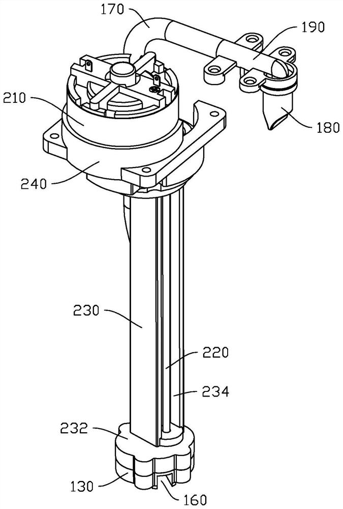
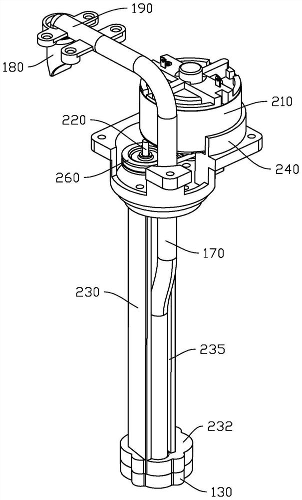
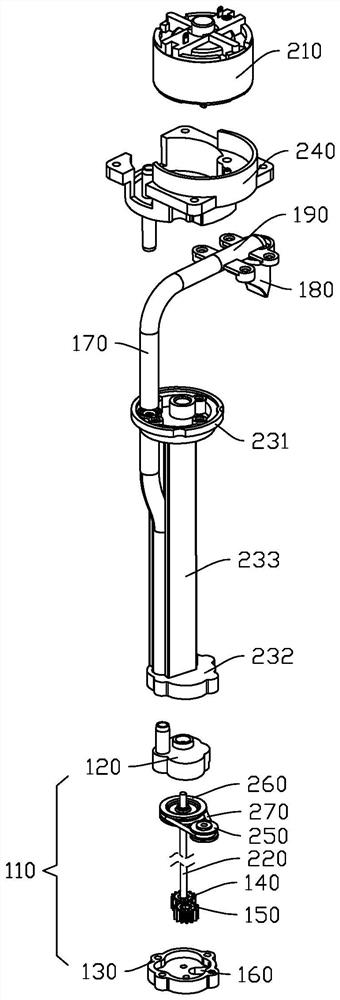
[0028] Refer Figure 1 to 3 The first aspect of the present invention provides a modular submersible gear pump including: a gearbox 110, in a liquid, and an active gear 140 and a driven gear 150, active gear 140, and driven in the gearbox 110. The gear 150 is engaged, and the gearbox 110 is provided with the inlet portion 160 and the liquid conduit 170; the motor 210 is located above the liquid, and the output end of the motor 210 is connected to the active gear 140 through the drive shaft 220, and the motor 210 is provided with a fixed seat 240, The holder 240 is connected to the gearbox 110 via the bracket 230.
[0029] The gearbox 110 is placed in the liquid, driven by the motor 210 to rotate, and drive the active gear 140 to rotate, the active gear 140 meshes the drive, and the liquid is inhaled from the inlet 160 into the gearbox 110, and then Output from the outlet pipe 170. Pumping liquid through the gear pump makes the liquid more uniform and delicate, the liquid is stable, and the extraction efficiency is high, and the user experience is improved.
[0030] Refer image 3 Wherein, the gearbox 110 includes a casing 120 and a cover 130, a casing 120, and a cover 130, and the casing 120 and the cover 130 are commonly defined to form a receiving chamber, the active gear 140 and the driven gear 150 are located in the accommodating chamber. The liquid pipeline 170 is disposed in the casing 120, and the inlet 160 is disposed in the box cover 130, the structure is simple, and the installation is convenient.
[0031] Refer Figure 1 to 3 The bracket 230 includes a fixing portion 231, the mounting portion 232, and the connecting portion 233, the fixing portion 231 and the mounting portion 232 are connected by a connecting portion 233, and the fixing portion 231 is connected to the motor 210, the mounting portion 232 is adapted to the cover 130, the mounting portion 232 is set in the casing 120 to fix the connection with the cover 130. By provided having a bracket 230, the gearbox 110 can be placed in a deeper place in the liquid, thereby capable of completely extracting the liquid, increasing the amount of liquid. Wherein, the connecting portion 233 is provided with a groove 234, and the drive shaft 220 is located within the recess 234, which can reduce the occupation area of the overall structure, so that the structure is reasonable and compact. It can be thought of that the connecting portion 233 is provided with mounting bit 235, and the liquid pipe 170 is located in the mounting bit 235, and the liquid pipe 170 is sequentially passed on the fixing portion 231, and the holder 240 extends upward. By placing the liquid pipe 170 in the mounting bit 235, the occupation area of the overall structure is reduced, and the structure is reasonably tight. It is readily understood that the liquid pipe 170 is provided with a duck spool valve 180. The duck spool valve 180 is a one-way valve, which prevents air from being hardened into the liquid pipe 170 to cause blockage, simple structure, simple operation, and improve user experience. Specifically, the duck spool valve 180 is fixedly coupled with the liquid bending pipe 190, and the other end of the liquid eluting pipe 190 is connected to the liquid pipe 170. By providing a liquid tube 190, it is convenient to connect to the duck nozzle valve 180 to improve the working efficiency.
[0032] The motor 210 is provided with a fixed seat 240, and the fixing portion 231 is fixed to the holder 240. The motor 210 is fixed by the fixing seat 240 to improve stability and safety. Wherein, the output of the motor 210 is provided with a first drive disc 250, and the transmission shaft 220 is provided with a second drive disc 260, and the first drive disc 250 and the second drive disc 260 are connected by a drive belt 270. The transmission belt 270 is transmitted, the structure is simple, and the operation is simple. It should be noted that the output of the motor 210 can also be connected by a gear set, or the output of the motor 210 directly connects to the drive shaft 220 through a coupling, and the present invention is not limited.
[0033] Refer Figure 4 The second aspect of the invention provides a soapper, including a modular submersible gear pump of the first aspect of the invention.
[0034]The modular submersible gear is pumped into the soap bottle, so that the gearbox 110 is located in the soap liquid, the motor 210 drives the drive shaft 220 to rotate, and drive the active gear 140 to rotate, the active gear 140 is engaged with the driven gear 150, and the liquid The gearbox 110 is sucked into the gearbox 110 from the inlet port 160, and then output from the liquid pipe 170. The soapper of the second aspect of the invention can directly cooperate with the modular diving gear pump to the soap bottle, easy to install, stable liquid content, high draw efficiency, and improve the user experience.
[0035] In the description of this specification, a description of the reference terms "one embodiment", "some embodiments", "schematic embodiment", "example", "specific example", or "some examples", etc., meant to combine the implementation Specific features, structures, materials, or features described in Examples or Examples are included in at least one embodiment or example of the present invention. In the present specification, the meaning of the above term is not necessarily referred to as the same embodiments or examples. Moreover, the specific features, structures, materials or features described may be combined in any one or more embodiments or examples.
[0036] While the embodiments of the present invention have been shown and described, those skilled in the art will appreciate that these examples can be made, modified, replaced, and variants without departing from the principles and dedication of the invention. The scope of the invention is defined by the claims and the like.