
Automatic cleansing fluid release water tank

An automatic cleaning and cleaning liquid technology, applied in water supply devices, sanitary equipment for toilets, buildings, etc., can solve problems such as easy failure, long time for dissolving, inconvenience, etc., to avoid circuit control, reliable work, and output. Liquid volume stabilization effect

Inactive Publication Date: 2014-09-03
董晓青
View PDF5 Cites 0 Cited by
  • Summary
  • Abstract
  • Description
  • Claims
  • Application Information

AI Technical Summary

Problems solved by technology

However, the problem with this method is that it is often necessary to add detergent, which is very inconvenient; another method is to use a so-called "blue bubble" water-soluble solid detergent, which is used by soaking it in the flushing water tank for a long time By slowly dissolving in the water, the purpose of cleaning while rinsing
But there are also some problems in this use of water-soluble solid cleaner: one, the solid toilet cleaner is placed inside the toilet tank for a long time, if the toilet usage rate is low, the dissolution time is too long, and the toilet The color of the discharged water is too strong, resulting in a waste of toilet cleaner, which can only last for three to five days, after which the fragrance of the toilet cleaner will not be smelled. The toilet agent does not have time to dissolve, and the water discharged from the toilet will be too weak to maintain the cleaning effect
Although the above-mentioned technical solution solves the problems existing in the traditional method, there are still deficiencies: since the solution is achieved by moving the buoy up and down, once it is blocked due to friction or foreign matter, it will not work normally and is prone to failure; On the one hand, the volume of the alcove space is determined, so the amount of detergent is also determined each time, and the amount of detergent cannot be adjusted according to the needs or the concentration of the detergent

Method used


Image

  • Automatic cleansing fluid release water tank
  • Automatic cleansing fluid release water tank
  • Automatic cleansing fluid release water tank

Examples


Embodiment Construction

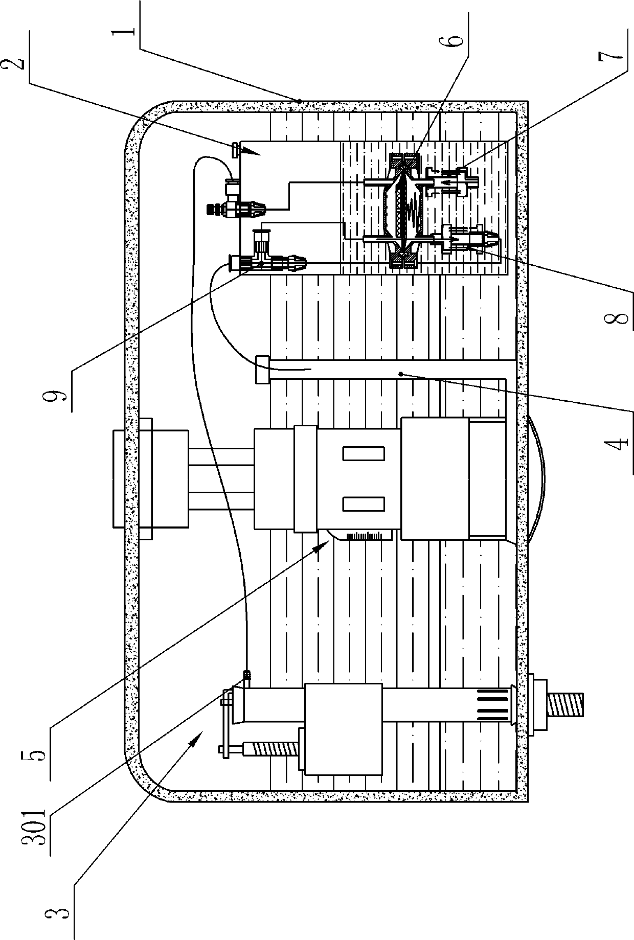
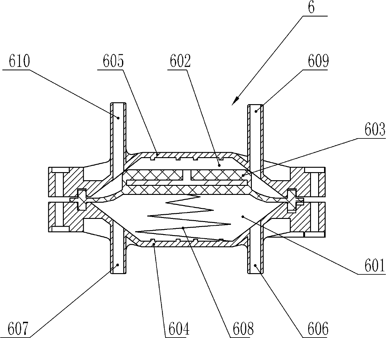
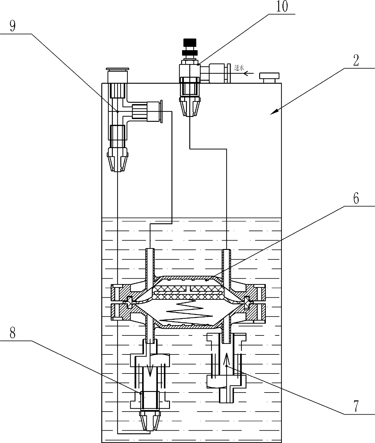
[0014] like figure 1 As shown, the automatic cleaning liquid release water tank includes a cleaning liquid box 2 containing cleaning liquid and a flushing water tank. The flushing water tank includes a box body 1, which is provided with a water part 3, an overflow pipe 4 and a flushing water tank. A valve assembly 5, a liquid aspirator 6, a liquid suction one-way valve 7, a liquid outlet one-way valve 8 and a water-liquid mixing joint 9 are arranged in the cleaning liquid box 2, and the liquid aspirator 6 is provided with a sealed liquid suction chamber 601 and the water pressure chamber 602, the liquid suction chamber 601 and the water pressure chamber 602 are isolated by an elastic diaphragm 603, and the liquid suction device 6 is provided with a reset mechanism for the elastic diaphragm 603, in this specific embodiment ,like figure 2 As shown, the liquid aspirator 6 includes a liquid suction chamber cover 604 and a water pressure chamber cover 605 with an arched concave c...


PUM


Abstract

The invention relates to an automatic cleaning liquid releasing water tank, which includes a cleaning liquid box containing cleaning liquid and a flushing water tank. The flushing water tank includes a box body, and the box body is provided with water fittings, overflow pipes and flushing valve assemblies, A liquid suction device, a liquid suction one-way valve, a liquid discharge one-way valve and a water-liquid mixing joint. The liquid suction device is provided with a sealed liquid suction chamber and a hydraulic pressure chamber. The space is separated by an elastic diaphragm, and a reset mechanism for the elastic diaphragm is provided in the liquid aspirator. The device of the present invention is equipped with a liquid suction device that uses water pressure as a power to change the volume of the liquid suction chamber to achieve the purpose of absorbing and extruding soap liquid. There are no moving parts, and there is no use wear and locking, so the work is reliable ; And because water pressure is used as power, no power supply, battery, etc. are needed, which avoids the tedious circuit control or environmental protection problems of the battery, and there is no danger of electricity.

Description

technical field [0001] The invention relates to a flushing water tank, in particular to an automatic cleaning liquid releasing water tank which can automatically release cleaning liquid when flushing. Background technique [0002] british john The flush toilet invented by Harrington as early as 1597 can be said to be a great contribution to human society. The flush toilet stores water through the attached flush water tank. After use, flush with the water in the flush water tank to maintain hygiene. The flush toilet ranks among the greatest inventions in human history. The flush water tank of the existing flush toilet usually includes a box body, which is provided with a water fitting, an overflow pipe and a flush valve assembly. The water fitting is provided with a water inlet valve and a float switch, and the float switch controls the water inlet valve. Close the water inlet valve when the water level is high, and open the water inlet valve to store water when the water l...

Claims


Application Information

Patent Timeline
Patent Type & Authority Patents(China)
IPC IPC(8): E03D9/03
Inventor 董晓青董浩灵
Owner 董晓青
Features
  • Generate Ideas
  • Intellectual Property
  • Life Sciences
  • Materials
  • Tech Scout
  • Unparalleled Data Quality
  • Higher Quality Content
  • 60% Fewer Hallucinations
Learn More