Advanced ceramic pipe type defueling pump

A technology of ceramic tubes and oil well pumps, which is applied in variable capacity pump parts, pumps, pump components, etc., can solve the problems of broken ceramic sleeves, low impact resistance, cracking and misalignment, etc., and achieves improved opening and closing speeds, The effect of increasing the area of ​​the liquid flow channel and increasing the degree of filling

Inactive Publication Date: 2010-02-17
吉林省大多天盛金属陶瓷技术有限公司
View PDF0 Cites 2 Cited by
  • Summary
  • Abstract
  • Description
  • Claims
  • Application Information

AI Technical Summary

Problems solved by technology

In order to prolong the service life of the oil pump, the current solution is to lay segmented sintered ceramic sleeves on the inner wall of the oil pump barrel and the outer wall of the plunger. Although this improvement is relatively excellent in wear resistance, high temperature resistance, and corrosion resistance , but the ceramic sleeve is prone to breakage, cracking and dislocation, and its impact resistance is low, which affects the performance of the oil well pump and is not conducive to long-term oil production operations. At the same time, the cost of sintered ceramics is high and the yield is low.

Method used


Image

  • Advanced ceramic pipe type defueling pump
  • Advanced ceramic pipe type defueling pump
  • Advanced ceramic pipe type defueling pump

Examples


Embodiment Construction

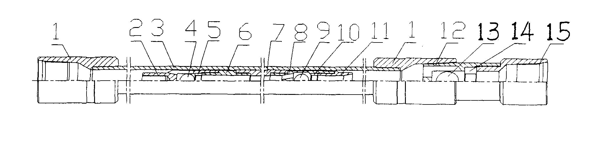
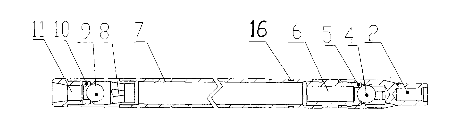
[0017] refer to figure 1 , figure 2 , 1. Pump barrel collar, 2. Upstream floating valve cover, 3. Ceramic pump barrel, 4. Upstream floating valve ball, 5. Upstream floating valve seat, 6 Plunger joint 7. Plunger, 8. Downstream Moving valve cover, 9. Downstream moving valve ball, 10. Downstream moving valve seat, 11. Pipe plug, 12. Fixed valve cover, 13. Fixed valve ball, 14. Fixed valve seat, 15. Lower coupling.

[0018] The body of the ceramic pump barrel oil pumping plunger 7 of the present invention is a tubing-shaped cylinder with a certain length. The outer layer of the ceramic pump barrel is a steel pump barrel, and the inner layer is in contact with the plunger, and the friction part is combined with the pump barrel. The integrated advanced ceramic layer is lined with grinding technology to make the smoothness and straightness of the ceramic layer on the inner wall of the pump barrel meet the requirements of use, while the plunger 7 is a steel cylinder, and the inner ...


PUM

PropertyMeasurementUnit
thicknessaaaaaaaaaa
hardnessaaaaaaaaaa
tensile strengthaaaaaaaaaa

Abstract

The invention relates to an advanced ceramic pipe type defueling pump, comprising a pump cylinder, a plunger piston, an upper traveling valve assembly, a lower traveling valve assembly and a strandingvalve assembly. The advanced ceramic pipe type defueling pump is characterized in that the inner wall of a steel-based pipe of the pump cylinder is provided with an advanced ceramic protection layerwith high temperature resistance, abrasion resistance and corrosion resistance, which is used as an lining; the outer surface of a rod body of the plunger piston is previously provided with grooves atintervals, alloy coatings with abrasion resistance and corrosion resistance is sprayed on the grooves, and zirconia toughening alumina ceramic rings are embedded into the surfaces of the alloy coatings inside the grooves.

Description

technical field [0001] The invention relates to the technical field of manufacturing oil production equipment, in particular to an oil well pump. Background technique [0002] The oil well pump is the key equipment to lift the crude oil to the ground by using the pressure difference between the front and back of the ball valve. Its quality directly affects the output and production cost of the oil field. The most vulnerable damages in the oil field are corrosion, wear and sand sticking. my country's oilfields have entered into the tertiary exploitation, and a series of oil-increasing measures such as water injection, carbon dioxide injection, and polymer injection have made the downhole environment increasingly harsh, and the sand content and corrosive substances in the well fluid are also increasing. It is also getting shorter and shorter, and the oil recovery cost of the oil field is increasing year by year. In order to prolong the service life of the oil pump, the current...

Claims


Application Information

Patent Timeline
Patent Type & Authority Applications(China)
IPC IPC(8): F04B47/02F04B53/16E21B43/00
Inventor 杨永利孙世杰陈春谱
Owner 吉林省大多天盛金属陶瓷技术有限公司
Why Eureka
Try Eureka