
Contact module for plug assembly

A technology for plug assemblies and contact modules, which is applied to contact parts, electrical components, parts of connecting devices, etc., can solve problems such as expensive manufacturing of electroplated plastic shells

Pending Publication Date: 2022-02-22
TAI LIAN SERVICES CO LTD
View PDF0 Cites 2 Cited by
  • Summary
  • Abstract
  • Description
  • Claims
  • Application Information

AI Technical Summary

Problems solved by technology

However, the manufacture of plated plastic housings is expensive

Method used


Image

  • Contact module for plug assembly
  • Contact module for plug assembly
  • Contact module for plug assembly

Examples


Embodiment Construction

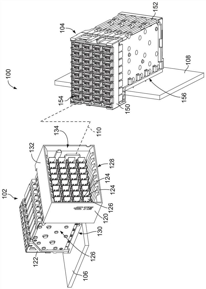
[0026] figure 1 is a perspective view of an exemplary embodiment of an electrical connector system 100 showing a first connector assembly 102 and a second connector assembly 104 that may be mated directly together. The first connector assembly 102 and / or the second connector assembly 104 may be referred to hereinafter individually as a "connector assembly" or collectively as a "connector assembly(s)". The first connector assembly 102 or the second connector assembly 104 may be a receptacle assembly, and the first connector assembly 102 or the second connector assembly 104 may be a plug assembly. In the description, first connector assembly 102 and corresponding components may be referred to as header assembly 102 and corresponding header components, and second connector assembly 104 and corresponding components may be referred to as receptacle assembly 104 and corresponding receptacle components.

[0027] The first and second connector assemblies 102 , 104 are each electrical...


PUM


Abstract

A plug assembly (102) includes a plug housing (120) and contact modules (122) coupled to the plug housing, the contact modules (122) each having a frame assembly (220) with a signal lead frame (230) and a dielectric frame (240). The dielectric frame includes a mating portion extension (242) at a front portion of the dielectric frame. The signal lead frame includes a mating portion (250) extending forward from the mating portion extension. Each contact module includes a ground shield (202) having a ground shield (302) providing electrical shielding for the mating portion. Each ground shield includes a shield wall (330) that forms a shield cavity (332) that receives a corresponding mating portion extension. Each ground shield includes a shield transition (344) to vary a depth of a shield cavity (322) along a length of the ground shield.

Description

technical field [0001] The subject of this article deals with connector components in general. Background technique [0002] Some electrical systems utilize connector assemblies, such as plug assemblies and socket assemblies, to interconnect two circuit boards, such as motherboards and daughter cards. Typically, a midplane assembly is provided between the motherboard and daughter cards. For example, the midplane assembly includes a midplane circuit board with header assemblies mounted to opposite sides of the midplane circuit board. The motherboard and daughter card each include a socket connector that mates to a corresponding header connector. Such electrical systems suffer from signal attenuation across the multiple interfaces of the midplane and receptacle assemblies. The receptacle assembly includes a contact module having contacts terminated to the circuit board. The header assembly includes contacts that are terminated to the midplane circuit board. [0003] Addit...

Claims


Application Information

Patent Timeline
Patent Type & Authority Applications(China)
IPC IPC(8): H01R12/72H01R12/73H01R13/02H01R13/502H01R13/648
CPCH01R12/724H01R12/732H01R13/648H01R13/502H01R13/02H01R13/6587H01R13/6589H01R13/6474H01R13/6471H01R13/04H01R13/518
Inventor W.彭T.R.明尼克D.E.希尔克K.E.本杰明E.L.亨格斯特D.A.特劳特J.B.麦克林顿J.D.皮克尔
Owner TAI LIAN SERVICES CO LTD
Learn More