Technique for determining a risk indicator for myopia

A risk indicator, myopia technology, applied in the direction of retinoscopy, health index calculation, equipment for testing eyes, etc.

Pending Publication Date: 2022-02-22
VIVIOR AG
View PDF0 Cites 3 Cited by
  • Summary
  • Abstract
  • Description
  • Claims
  • Application Information

AI Technical Summary

Problems solved by technology

It can also be caused by the structure of the visual environment, where objects in the peripheral field of view are at different distance

Method used


Image

  • Technique for determining a risk indicator for myopia
  • Technique for determining a risk indicator for myopia
  • Technique for determining a risk indicator for myopia

Examples


Embodiment Construction

[0120] In the following, but not limited to, specific details are set forth in order to provide a thorough understanding of the present disclosure. However, it will be apparent to those skilled in the art that the present invention may be used in other embodiments that may vary from the details set forth below.

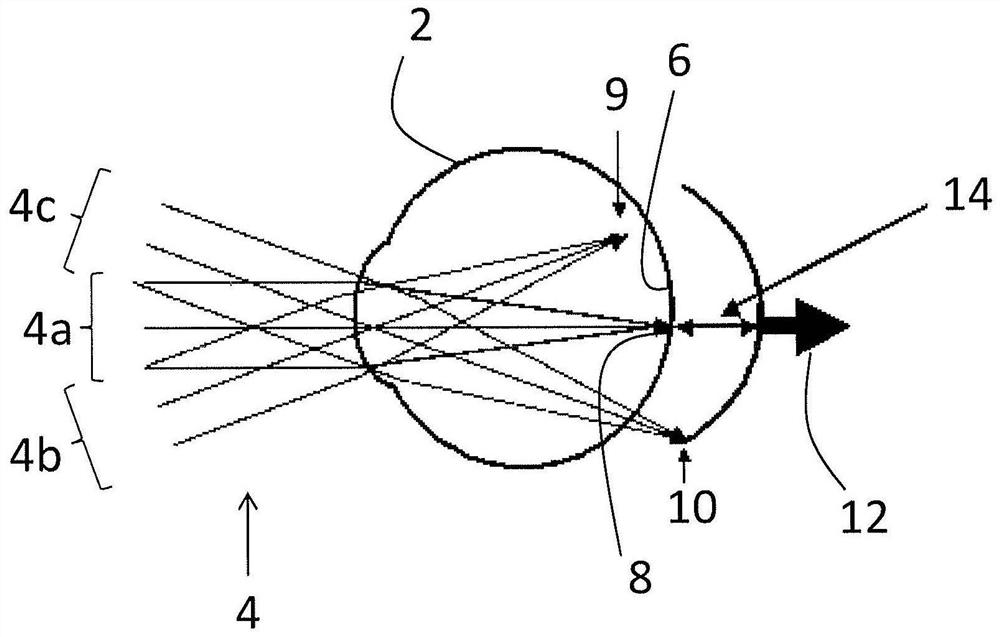
[0121] figure 1 A schematic diagram of a cross-section of the user's eye 2 is shown. In the following, reference will be made to figure 1 Eye 2 shown in to discuss possible causes of myopia. It should be noted that figure 1 The representations do not necessarily show a specific point in time, but show different situations in the same figure for illustrative purposes.

[0122] Such as figure 1 As shown, light 4 enters the eye 2 from the left. Ray 4 passes through the pupil of eye 2 and is captured by the lens of eye 2 ( figure 1 Both the pupil and the lens are not shown) focusing. Ideally, ie in order to obtain a sharp image, the light rays 4 are focused onto t...


PUM


Abstract

A system is provided for determining a risk indicator for myopia. The system comprises a wearable device configured to be attached to a body of a user. The wearable device comprises at least one distance sensor configured to determine at least a first distance value indicative of a distance between the wearable device and an object located in a central vision zone of the user and a second distance value indicative of a distance between the wearable device and an object located in a peripheral vision zone of the user. The system further comprises a control unit configured to determine, based on the first distance value and the second distance value, a risk indicator for myopia. Further, a method and a computer program product are provided.

Description

technical field [0001] This disclosure relates to the field of ophthalmology. More precisely, the present disclosure relates to a technique for determining a risk indicator of myopia. In particular, the risk indicator may indicate the risk of myopia onset and / or progression. The technology can be embodied in at least one system and / or at least one method. Background technique [0002] It is well known that nearsightedness (myopia), especially in children, can be caused by eye growth. In this case, the growth of the eye causes the eye to be too large, so the image is not formed on the retina (as it should be), but in front of the retina, inside the eye. [0003] It is further known that a phenomenon known as "hyperopic defocus" (where an image is formed behind the retina of the eye) can cause the eye to grow, resulting in myopia. Further details on myopia in general and on the aforementioned phenomena are described, for example, in Flitcroft, D.I. (2012): "The complex int...

Claims


Application Information

Patent Timeline
IPC IPC(8): A61B3/103A61B3/11A61B3/117G16H50/20G16H50/30G16H50/50
CPCA61B3/103A61B3/112A61B3/1173G16H50/30G16H50/50G16H50/20A61B3/113G02C11/10G02C2202/24G16H40/63G16H40/67A61B2562/0219A61B3/0091A61B3/14A61B5/065A61B5/1114A61B5/6803A61B5/7275
Inventor 帕维尔·扎哈罗夫丹尼尔·伊恩·弗利克罗夫特迈克尔·姆罗亨
Owner VIVIOR AG
Why Eureka
Try Eureka