
Recognition method for automatically detecting position of lifting lug

A recognition method and automatic detection technology, applied in image data processing, instrumentation, calculation, etc., can solve problems such as large amount of calculation, high cost, and difficulty in matching feature points, so as to improve work efficiency and reduce waste.

Inactive Publication Date: 2018-11-30
ZHONGBEI UNIV
View PDF2 Cites 7 Cited by
  • Summary
  • Abstract
  • Description
  • Claims
  • Application Information

AI Technical Summary

Problems solved by technology

The binocular vision system uses two parallel-installed cameras to collect image information separately and process them simultaneously, and uses binocular parallax to calculate the distance of objects, which can directly solve the depth information of objects in the scene; but its cost is high, and feature point matching is difficult. Large amount of calculation

Method used


Image

  • Recognition method for automatically detecting position of lifting lug
  • Recognition method for automatically detecting position of lifting lug
  • Recognition method for automatically detecting position of lifting lug

Examples


Embodiment Construction

[0050] The present invention will be described in further detail below in conjunction with the accompanying drawings and specific embodiments.

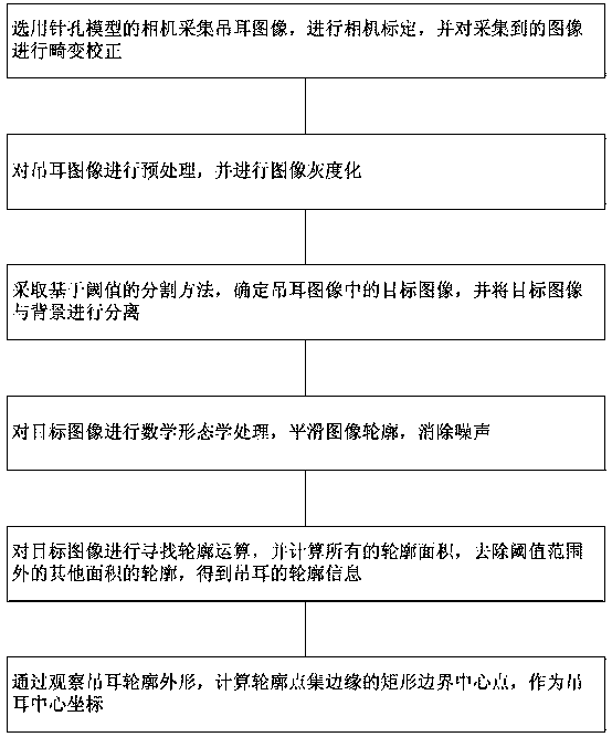
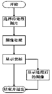
[0051] Such as figure 1 and figure 2 as shown, figure 1 It is a schematic flow chart of the identification method for automatically detecting the position of the lifting lug of the present invention, figure 2 It is a logical schematic diagram of the recognition method for automatically detecting the position of the lifting lug provided by the present invention. This method is identified by the following device for automatically identifying the hoisting position, which device includes (1) a cylinder with a diameter of 124 mm and a length of 62 mm for the pressure vessel; (2) a metal strip with a width of 10 mm for the lifting lug of the pressure vessel; (3) ) acA1300-60gm model camera produced by industrial camera BASLER; (4) computer.

[0052] Design the detection device for lifting lug position, including the design of hardware...


PUM


Abstract

The invention discloses a recognition method for automatically detecting the position of a lifting lug. The method comprises the steps of carrying out OpenCV-based camera calibration on a camera for an imaging model of the camera and carrying out distortion correction on a collected image; through taking Microsoft Visual Studio 2010 as an algorithmic compilation platform and combining an OpenCV2.4.9 open source image library, developing a detection and recognition algorithm for the mounting position of the lifting lug of a pressure vessel; processing an image of the lifting ear to obtain the contour of the lifting lug and the coordinate of the center point of the lifting lug; and analyzing and processing the data. The method has the advantages that according to the design algorithm, the maximum error of the coordinate point is 2.5mm and the minimum error can be up to 0.1mm; by analyzing the relationship between the data and the image, when the position coordinate of the lifting lug atthe central vision field of the camera is more inaccurate and is more deviated from the center position, the obtained coordinate error is larger; and through the method disclosed by the invention, theposition coordinate of the lifting lug can be found.

Description

technical field [0001] The invention relates to a recognition method for automatically detecting the position of a lifting lug, which relates to target recognition and positioning based on machine vision. Background technique [0002] As a large industrial country, with the continuous progress of modern industry, the continuous development of science, and the development of economy, the requirements for industry are getting higher and higher. A complete automation system is especially necessary, which can not only improve labor conditions, but also reduce The labor intensity of workers can be guaranteed, and production safety can be ensured, while productivity can be greatly improved. [0003] In the current process of hoisting pressure vessels in factories, the position of lifting lugs is still manually identified, which is not only inefficient, but also poses a threat to human life. If machine vision technology is used to convert the image into a computer-recognizable dig...

Claims


Application Information

Patent Timeline
Patent Type & Authority Applications(China)
IPC IPC(8): G06T7/11G06T7/136G06T7/194G06T7/70G06T7/80
CPCG06T7/11G06T7/136G06T7/194G06T7/70G06T7/80G06T2207/30164G06T2207/30208
Inventor 王福杰俞恒杰杨琦陆辉山薛卓兰
Owner ZHONGBEI UNIV
Learn More