
Inlet cone for an aircraft turbine engine and associated aircraft turbine engine

A turbine engine and aircraft technology, applied in the field of gas turbine engines and turbine engines, can solve problems such as insufficient separation, and achieve the effects of simple design, reduced size, and high reliability

Pending Publication Date: 2022-02-22
SAFRAN AIRCRAFT ENGINES SAS
View PDF1 Cites 0 Cited by
  • Summary
  • Abstract
  • Description
  • Claims
  • Application Information

AI Technical Summary

Problems solved by technology

Therefore, this solution is insufficient to quickly and completely separate the ice layer formed on the tip of the inlet cone

Method used


Image

  • Inlet cone for an aircraft turbine engine and associated aircraft turbine engine
  • Inlet cone for an aircraft turbine engine and associated aircraft turbine engine
  • Inlet cone for an aircraft turbine engine and associated aircraft turbine engine

Examples


Embodiment Construction

[0030] As is customary in this application, the terms "inner" and "outer" and "inner" and "outer" are defined radially with respect to the longitudinal axis X of the aircraft engine of the turbine engine. Thus, a cylinder extending along the axis X of the engine comprises an inner surface facing the shaft of the engine and an outer surface opposite its inner surface. "Axial" or "axially" means any direction parallel to the axis X, and "transversely" or "transversely" means any direction perpendicular to the axis X. Similarly, the terms "upstream" and "downstream" are defined relative to the direction of airflow in the turbine engine.

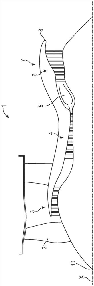
[0031] figure 1 A twin-flow turbine engine 1 is shown. However, this is not limiting and the turbine engine may be another type of turbine engine, eg a turboprop.

[0032] The turbine engine 1 extends along a longitudinal axis X and comprises, from upstream to downstream in the direction of air flow, a fan 2, one or more compressor stages (e...


PUM


Abstract

The present invention concerns an inlet cone (10) for an aircraft turbine engine (1), comprising a frustoconical body (12) and a tip (11) made from elastically deformable material attached to an end (12p) of smaller diameter of the body (12), the tip (11) comprising an apex configured to be situated on an axis of rotation (X) of the cone and an attachment base (11p) for attachment to the end (12p). According to the invention, the base (11p) has a generally circular or oval shape, this base extending in a connecting plane (P), and the connecting plane (P) is inclined relative to a transverse plane (T) perpendicular to the axis of rotation (X). The present invention further concerns an aircraft turbine engine (1), comprising such an inlet cone (10).

Description

technical field [0001] The field of the invention is that of turbine engines, in particular gas turbine engines, such as but not limited to turbojets or aircraft turboprops. [0002] The invention more particularly relates to an air inlet cone for a turbine engine. Background technique [0003] The prior art includes inter alia documents GB-A-1 557 856, FR-A1-2 943 726, FR-A1-3 027 878, FR-A1-2 943 725 and FR-A1-2 898 939. [0004] It is known from the prior art that a turbine engine extends along a longitudinal axis and comprises, from upstream to downstream in the direction of air flow, a fan, one or more compressor stages (for example, a low-pressure compressor and a high-pressure compressor), a combustion chamber chamber, one or more turbine stages (eg, high pressure turbine and low pressure turbine), and exhaust nozzles. [0005] Typically, such turbine engines further comprise an upstream air inlet cone mounted to the fan, for example by a generally annular upstream ...

Claims


Application Information

Patent Timeline
Patent Type & Authority Applications(China)
IPC IPC(8): F02C7/04F01D25/02
CPCF02C7/04F01D25/02F05D2250/232F05D2250/314F05D2250/73F05D2300/431B64C11/14B64D15/16F01D5/025Y02T50/60F01D5/02F02C7/047F05D2220/323F05D2240/24
Inventor 巴普蒂斯特·勒内·罗杰·巴通奈特奥尔本·弗朗索瓦·路易斯
Owner SAFRAN AIRCRAFT ENGINES SAS
Learn More