
Eureka
For R&D, Eureka makes reading and utilizing patents & technical documents easy.
Eureka AIR
Designed for self-driven R&D workflows. Generate viable solutions, solve complex R&D challenges, empower your innovation with AI.

Eureka Materials
Designed for material experts only. Revolutionize your material R&D, from search, analyze, to developing new materials.

TechResearch
Generate reliable direction feasibility study reports for your R&D in just a few steps.

TechSeek
Discover and master advanced knowledge NOW. Basics, ideas, possibilities, all at once.

TechMind
As an expert in R&D Theories, TechMind can generates customized viable solutions instantly.

TechRisk
Analyze your overall solution with one click, know your potential R&D risks in advance.

TechMonitor
Get weekly tech updates, stay abreast of the latest tech innovations and key insights.
Wave-soldering carrier dismounting and reflowing device and method
A reflow device and wave soldering technology, applied in auxiliary devices, welding equipment, manufacturing tools, etc., can solve the problems of low degree of automation and high labor intensity, and achieve the effect of high degree of automation, improved separation efficiency, and improved removal efficiency.
- Summary
- Abstract
- Description
- Claims
- Application Information
AI Technical Summary
Problems solved by technology
Method used
Image

Examples
Embodiment 1
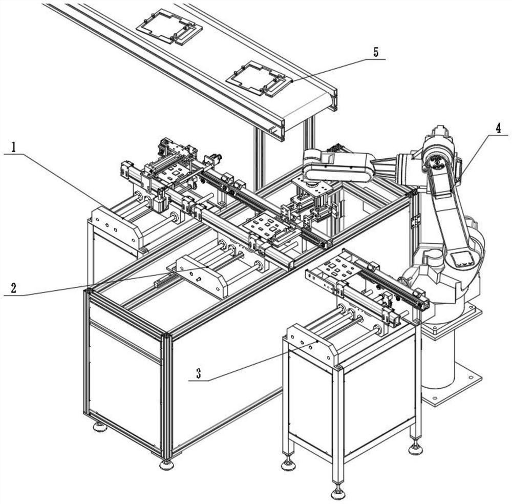
[0041] Please refer to the attached Figure 1-6 , a wave soldering carrier removal and reflow device, including a release mechanism 1, a separation mechanism 2, a clamping mechanism 4, a PCB board transport mechanism 3 and a tooling reflow mechanism 5; the output end of the release mechanism 1 is connected to the input end of the separation mechanism 2 , the clamping mechanism 4 is located on one side of the separation mechanism 2, and is used to clamp the PCB board and the tooling in the separation mechanism 2 to the PCB board transport mechanism 3 and the tooling return mechanism 5 respectively.
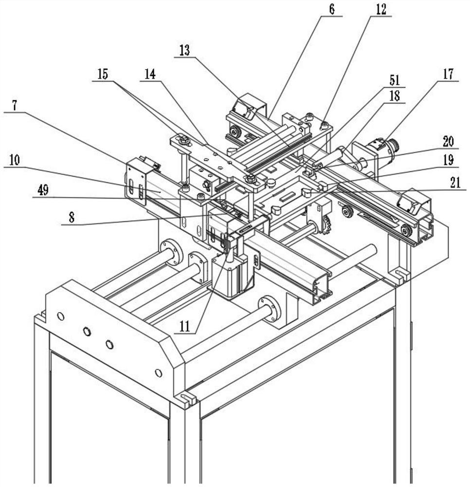
[0042] In this embodiment, the wave soldering carrier 19 includes a tooling and a PCB board embedded in the tooling. The front end of the tooling includes a folded pressing plate 51. When the pressing plate 51 is turned over to the top of the PCB, the PCB is fastened and positioned; the pressing plate 51 is turned over to the PCB. When the board is on the plane, the PCB board will ...
Embodiment 2
[0058] A method for disassembling and reflowing a wave soldering carrier 19 includes the device structure in Embodiment 1, and includes a control center of the overall device. In the embodiment, the signals of each mechanism are transmitted to the control center and uniformly deployed through the control center. Specifically include the following steps:
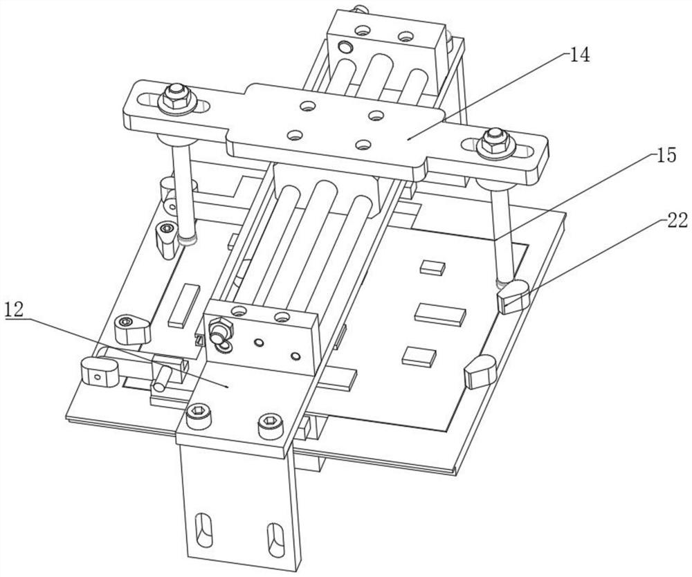
[0059] S01: The wave soldering carrier 19 enters the release mechanism 1, and the turning unit turns the pressure plate to the plane where the PCB board is located; the moving plate 14 in the toggle unit drives the lever 15 to reciprocate, so that the buckle 21 on the tooling is unscrewed, at this time The wave soldering carrier 19 is in a released state.
[0060] Step S01 specifically includes:
[0061] S011: The first photoelectric detector 7 detects that the wave soldering carrier 19 enters the release mechanism 1, and the control center controls the first blocking cylinder 11 to extend; the control center controls the fi...
PUM
 Abstract
Description
Claims
Application Information
 - R&D Engineer
- R&D Manager
- IP Professional
- Industry Leading Data Capabilities
- Powerful AI technology
- Patent DNA Extraction
Browse by: Latest US Patents, China's latest patents, Technical Efficacy Thesaurus, Application Domain, Technology Topic, Popular Technical Reports.
© 2024 PatSnap. All rights reserved.Legal|Privacy policy|Modern Slavery Act Transparency Statement|Sitemap|About US| Contact US: help@patsnap.com