
S-shaped joint for steel structure

A technology for steel structures and joints, which is applied in the direction of building structures and buildings, and can solve problems such as large internal forces and affecting structural safety.

Active Publication Date: 2022-02-25
CHINA POWER CONSRTUCTION GRP GUIYANG SURVEY & DESIGN INST CO LTD
View PDF6 Cites 0 Cited by
  • Summary
  • Abstract
  • Description
  • Claims
  • Application Information

AI Technical Summary

Problems solved by technology

[0003] Using the existing steel structure connection method, due to the large internal force at the node position under the action of the support displacement, it will seriously affect the structural safety

Method used


Image

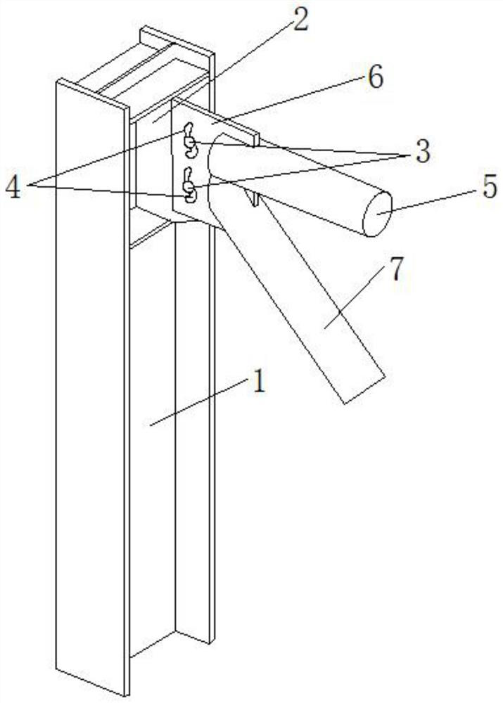
  • S-shaped joint for steel structure
  • S-shaped joint for steel structure
  • S-shaped joint for steel structure

Examples


Embodiment Construction

[0026] In order to enable those skilled in the art to better understand the solution of the present application, the technical solution in the embodiment of the application will be clearly and completely described below in conjunction with the accompanying drawings in the embodiment of the application. Obviously, the described embodiment is only It is an embodiment of a part of the application, but not all of the embodiments. Based on the embodiments in this application, all other embodiments obtained by persons of ordinary skill in the art without creative efforts shall fall within the scope of protection of this application.

[0027] In this application, the terms "upper", "lower", "left", "right", "front", "rear", "top", "bottom", "inner", "outer", "middle", The orientations or positional relationships indicated by "vertical", "horizontal", "horizontal", and "longitudinal" are based on the orientations or positional relationships shown in the drawings. These terms are main...


PUM


Abstract

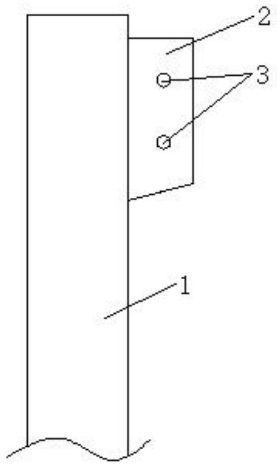
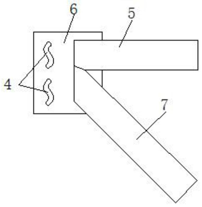
The invention discloses an S-shaped joint for a steel structure. The device comprises a steel column, a connecting plate and a bolt, wherein an S-shaped oblong hole is formed in the connecting plate; the steel column is connected with the column connecting plate, and the column connecting plate is fixedly connected with the bolt; after the bolt is fixed to the connecting plate, the bolt penetrates into an S-shaped oblong hole and then is connected with a nut. The S-shaped oblong hole is formed on the basis of a traditional steel structure node, such as an inter-column supporting connection process, and the bolt is fixed on the other connecting plate, so that the connecting plate can slide through the S-shaped oblong holes when a support is moved down, vertical internal force is released through sliding when the support is settled, and under the action of earthquakes and wind loads, a node constrains the horizontal direction to transfer horizontal forces. By means of the method, structural damage and collapse caused by foundation deformation can be effectively avoided, and steel structure buildings (such as light steel workshops and the like) built under the large-deformation foundation conditions of high fill, permafrost regions and the like have good economic effects.

Description

technical field [0001] The invention relates to the technical field of steel structure connection nodes, in particular to a slidable "S" type node for steel structures. Background technique [0002] The current steel structure connection mainly adopts welding or bolt connection, but neither connection can adapt to the large deformation of the steel structure. The large deformation mainly includes the following situations: 1) High backfill soil, uneven distribution of soil layers, resulting in large settlement difference; Larger foundation deformation; 3) under the action of low-frequency vertical deformation; 4) under the action of high-frequency wind load and seismic horizontal force. [0003] Using the existing steel structure connection method, due to the large internal force at the node position under the action of the support displacement, it will seriously affect the structural safety. Contents of the invention [0004] The object of the present invention is to pro...

Claims


Application Information

Patent Timeline
Patent Type & Authority Applications(China)
IPC IPC(8): E04B1/24E04B1/58
CPCE04B1/2403E04B1/5812E04B2001/2406E04B2001/2433E04B2001/2439E04B2001/5862Y02E10/50
Inventor 胡智友吕军姚斌李晓彬
Owner CHINA POWER CONSRTUCTION GRP GUIYANG SURVEY & DESIGN INST CO LTD
Learn More