Supercharge Your Innovation With Domain-Expert AI Agents!

State detection method and system for a steam turbine low-pressure cylinder spraying device

A spray device and state detection technology, applied in the field of nuclear power, can solve the problems of falling steel pipes, high risk of falling, and slippery, and achieve the effects of accurate nozzle state, reduction of operation risks, and elimination of errors.

Active Publication Date: 2022-02-25
CHINA GENERAL NUCLEAR POWER OPERATION +2
View PDF4 Cites 0 Cited by
  • Summary
  • Abstract
  • Description
  • Claims
  • Application Information

AI Technical Summary

Problems solved by technology

However, the above-mentioned processing method has the following disadvantages: the workload of setting up scaffolding is very large, and it is necessary to build a scaffold that can reach all nozzle positions; the inside of the low-pressure cylinder is wet and slippery, the light is not good, and the drop exceeds 10m, and there are scaffolding personnel and inspectors. High risk of falling; the risk of falling objects is high, and it is easy to happen when the scaffolding in the low-pressure cylinder falls and the titanium tube of the condenser is damaged by falling steel pipes and scaffolding plates; during the overhaul, the compressed air pressure is usually only 0.5-0.6MPa (standard 0.8MPa), And there are fluctuations. The evaluation of the status of the nozzle needs to be judged by the strength of the gas ejected by the personnel. Therefore, the subjective factors of the person are greatly affected, and an accurate evaluation cannot be made.

Method used


Image

  • State detection method and system for a steam turbine low-pressure cylinder spraying device
  • State detection method and system for a steam turbine low-pressure cylinder spraying device
  • State detection method and system for a steam turbine low-pressure cylinder spraying device

Examples


Embodiment Construction

[0047]In order to have a clearer understanding of the technical features, purposes and effects of the present invention, the specific implementation manners of the present invention will now be described in detail with reference to the accompanying drawings.

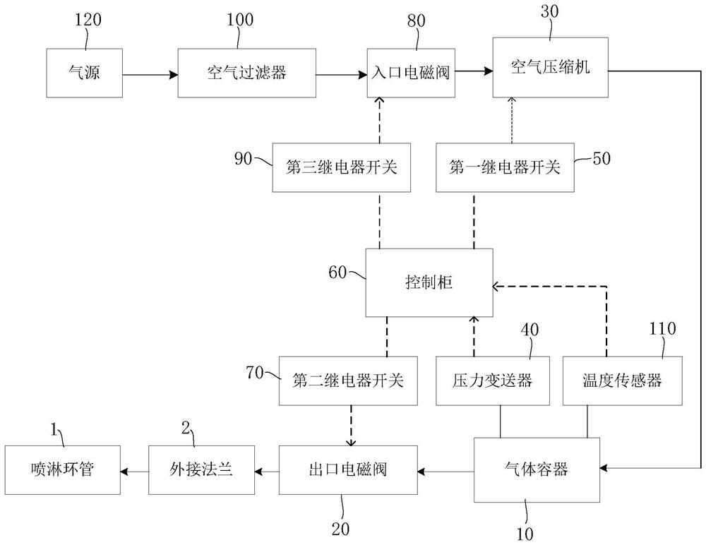
[0048] The method for detecting the state of the spraying device of the low-pressure cylinder of the steam turbine of the present invention realizes the detection of the spraying device on the low-pressure cylinder of the steam turbine, so as to obtain whether the spraying device is blocked or not. The spraying device on the low-pressure cylinder usually includes a spraying ring pipe and a plurality of nozzles distributed on the spraying ring pipe at intervals. Generally, each low-pressure cylinder is equipped with a sprinkler device for the exhaust steam of the final blades at the front and rear ends.

[0049] refer to figure 1 , the method for detecting the state of the steam turbine low-pressure cylinder spray device...


PUM


Abstract

The invention discloses a state detection method and system for a steam turbine low-pressure cylinder spraying device. The state detection method for the steam turbine low-pressure cylinder spraying device comprises the steps of: S1, connecting a gas container with an external flange of a spraying ring pipe through an outlet electromagnetic valve, and making the outlet electromagnetic valve in a closed state; S2, supplying gas to and pressurizing the gas container to enable the internal pressure of the gas container to reach a first preset value; S3, opening the outlet electromagnetic valve, and communicating the gas container with the spraying ring pipe; S4, when the internal pressure of the gas container is reduced to a second preset value, recording the time required when the internal pressure is reduced to the second preset value, and recording the time as pressure relief time; and S5, comparing the pressure relief time with the standard pressure relief time, and if the pressure relief time is longer than the standard pressure relief time, indicating that part or all of the nozzles on the spraying ring pipe are blocked. The state of the nozzles can be checked without erecting a scaffold and entering the low-pressure cylinder, so that the operation risk is reduced; the error of subjective evaluation of inspectors is eliminated, and the state of the nozzles is precisely evaluated.

Description

technical field [0001] The invention relates to the technical field of nuclear power, in particular to a method and system for detecting the state of a low-pressure cylinder spray device of a steam turbine. Background technique [0002] The low-pressure cylinder spraying device of the steam turbine is to spray condensed water to the diffusion section of the low-pressure cylinder after the exhaust of the last stage blade to achieve the cooling effect when the unit is running at no load or at low power, so as to reduce the deformation of the cylinder and avoid the excessive temperature of the exhaust cylinder from causing the unit to jump off the plane. The spraying devices for the low-pressure cylinders of steam turbines of various types of million-dollar nuclear power units are similar. Generally, there are spray ring pipes for the exhaust of the last stage blades at the front and rear ends of each low-pressure cylinder. There are 6 spray ring pipes in total for 3 low-pressu...

Claims


Application Information

Patent Timeline
Patent Type & Authority Applications(China)
IPC IPC(8): F01D25/12F01D21/00
CPCF01D25/12F01D21/003
Inventor 贾凯利蒋乔竹徐万年苑令辉姜昌国张亚辉周功林余雪晴阮冰
Owner CHINA GENERAL NUCLEAR POWER OPERATION
Features
  • R&D
  • Intellectual Property
  • Life Sciences
  • Materials
  • Tech Scout
  • Unparalleled Data Quality
  • Higher Quality Content
  • 60% Fewer Hallucinations
Learn More