Underground reservoir capacity measuring method based on gas-liquid diffusion concentration

An underground reservoir and measurement method technology, applied in the direction of volume measurement instrument/method, liquid/fluid solid measurement, measurement device, etc., can solve the problems of complicated operation, high cost, slow data, etc., and achieve the effect of simple operation and low cost

Active Publication Date: 2022-02-25
CHINA UNIV OF MINING & TECH (BEIJING)
View PDF10 Cites 0 Cited by
  • Summary
  • Abstract
  • Description
  • Claims
  • Application Information

AI Technical Summary

Problems solved by technology

[0005] Aiming at the current problem of cumbersome operation, slow data acquisition and high cost in the current measurement method of underground reservoir storage capacity, the present invention provides a convenient and easy-to-operate, low-cost and real-time monitoring of the existing water volume and internal environment of the underground reservoir based on the gas-liquid diffusion concentration. Storage capacity measurement method

Method used


Image

  • Underground reservoir capacity measuring method based on gas-liquid diffusion concentration
  • Underground reservoir capacity measuring method based on gas-liquid diffusion concentration

Examples


Embodiment 1

[0058] Embodiment 1 The preselected gas is N which is poorly soluble in water 2 .

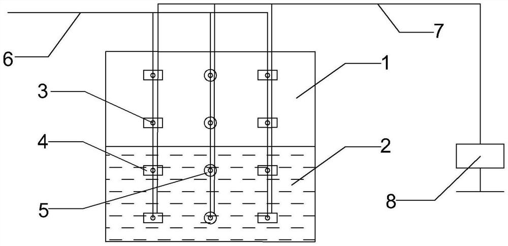
[0059] In this embodiment, the pre-selected liquid is NaCl, and the gas is N which is hardly soluble in water. 2 , there are six distribution points 3, six liquid concentration sensors 4 and six gas concentration sensors 5 in the underground reservoir, and the pre-selected liquid quality is 5kg and the gas quality is 3kg in each distribution point 3. The original concentrations measured by the six liquid concentration sensors 4 are 0.02%, 0.019%, 0.021%, 0, 0, 0 respectively, and the concentrations after stabilization are 0.080%, 0.079%, 0.081%, 0, 0, 0. The original concentrations measured by the six gas concentration sensors 5 are 0, 0, 0, 78.001%, 77.999%, 78.001%, respectively, and the stable concentrations are 0, 0, 0, 78.051%, 78.049%, 78.051%.

[0060] According to the volume calculation formula of the existing water body 2 of the underground reservoir The volume of the existing wate...

Embodiment 2

[0061] Example 2 The preselected gas is He which is soluble in water.

[0062] In this embodiment, the pre-selected liquid is NaCl, and the gas is water-soluble He. There are six deployment points 3, six liquid concentration sensors 4 and six gas concentration sensors 5 in the underground reservoir, and they are placed at each distribution point. 3 Pre-selected liquid quality is 5kg, gas quality is 3kg. The original concentrations measured by the six liquid concentration sensors 4 are 0.02%, 0.019%, 0.021%, 0, 0, 0 respectively, and the concentrations after stabilization are 0.080%, 0.079%, 0.081%, 0, 0, 0. The original concentrations measured by the six gas concentration sensors 5 are 0, 0, 0, 0, 0, 0%, respectively, and the stable concentrations are 0.010%, 0.009%, 0.011%, 0.051%, 0.049%, 0.050%. According to the calculation formula for the volume of the existing water body 2 of the underground reservoir, the volume of the existing water body 2 of the underground reservoir ...


PUM


Abstract

The invention discloses an underground reservoir capacity measuring method based on gas-liquid diffusion concentration. The method comprises the steps of measuring the volume of an existing water body of an underground reservoir and measuring the volume of a cavity of the underground reservoir. Pre-selected gas and liquid are input into corresponding arrangement throwing points through throwing channels, the gas-liquid concentration measured in real time is transmitted to a computer system through a transmission line by means of liquid and gas concentration sensors, the system carries out operation solution on gas-liquid concentration data matched with time and space information, the volume of the existing water body of the underground reservoir and the volume of the cavity of the underground reservoir are obtained, and the volumes are added to obtain the capacity of the underground reservoir. The underground reservoir capacity measuring method provided by the invention has the advantages of being convenient to operate, low in cost, capable of monitoring the existing water storage amount and the internal environment of the reservoir in real time and the like.

Description

technical field [0001] The invention relates to the technical field of reservoir capacity measurement, in particular to a method for measuring underground reservoir capacity based on gas-liquid diffusion concentration. Background technique [0002] Underground reservoir is an alternative and supplementary water resource regulation and storage method proposed to solve the shortcomings of surface reservoirs, such as large evaporation, short water storage period, and large occupied area. The role of underground reservoirs is to adjust the spatial and temporal distribution of water resources for human use, artificially store surface surplus water in underground water storage structures during high water seasons or when water consumption is low, and change the spatial distribution of water resources; The storage capacity should be used in the dry season, which adjusts the time distribution of water resources. China is also vigorously promoting the use of underground space to bui...

Claims


Application Information

Patent Timeline
IPC IPC(8): G01F22/00
CPCG01F22/00
Inventor 徐超王凯吴世敏马世豪苏明清李晓敏赵伟郭海军
Owner CHINA UNIV OF MINING & TECH (BEIJING)
Why Eureka
Try Eureka