Oral cavity scanner

A technology for scanners and oral cavity, which is applied in the field of oral scanners, and can solve the problems of transparent heating film damage, optical image deformation, and increasing the brightness of projection light sources, etc.

Pending Publication Date: 2022-03-01
QISDA OPTRONICS (SUZHOU) CO LTD +1
View PDF0 Cites 0 Cited by
  • Summary
  • Abstract
  • Description
  • Claims
  • Application Information

AI Technical Summary

Problems solved by technology

Install a heater behind the reflector to heat the reflector. The main material of the reflector is glass, and its heat conduction effect is not good.
Install the heater on the remote IOS body, and then conduct the heat to the back of the reflective chip at the front of the IOS through a material with high thermal conductivity. The heat conduction path is too long, and the heat conduction of the reflector itself is not good and consumes more power.
A transparent heating film is set on the transparent optical component to completely cover the optical effective area, but the light is refracted back and forth many times, resulting in too much light loss, which needs to be compensated by increasing the brightness of the projection light source and greatly increasing power consumption; transparent The microstructure inside the heating film is inconsistent / uneven, which will cause the deformation of the optical image and cause the loss of accuracy of the measurement results; the process of laminating the transparent heating film on the reflective lens cannot achieve complete flatness, such slight unevenness Bubbles / impurities will cause distortion of the optical image, resulting in loss of accuracy of the measurement results; during the cleaning (including brushing) / sterilization process of the IOS after use, the transparent heating film may be damaged, resulting in a period of use after leaving the factory The unevenness / bubbles / impurities that appear later will cause the deformation of the optical image, resulting in the loss of accuracy of the measurement results

Method used


Image

  • Oral cavity scanner
  • Oral cavity scanner
  • Oral cavity scanner

Examples


Embodiment Construction

[0021] In order to have a further understanding of the purpose, structure, features and functions of the present invention, the detailed description is as follows in conjunction with the embodiments.

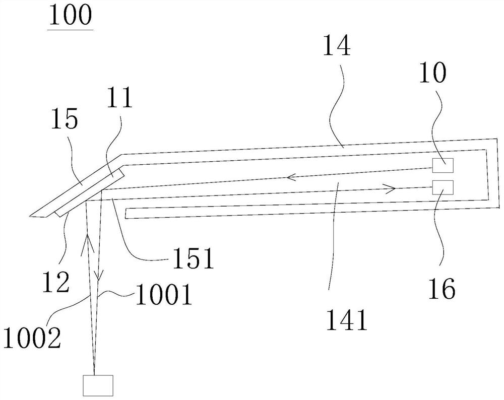
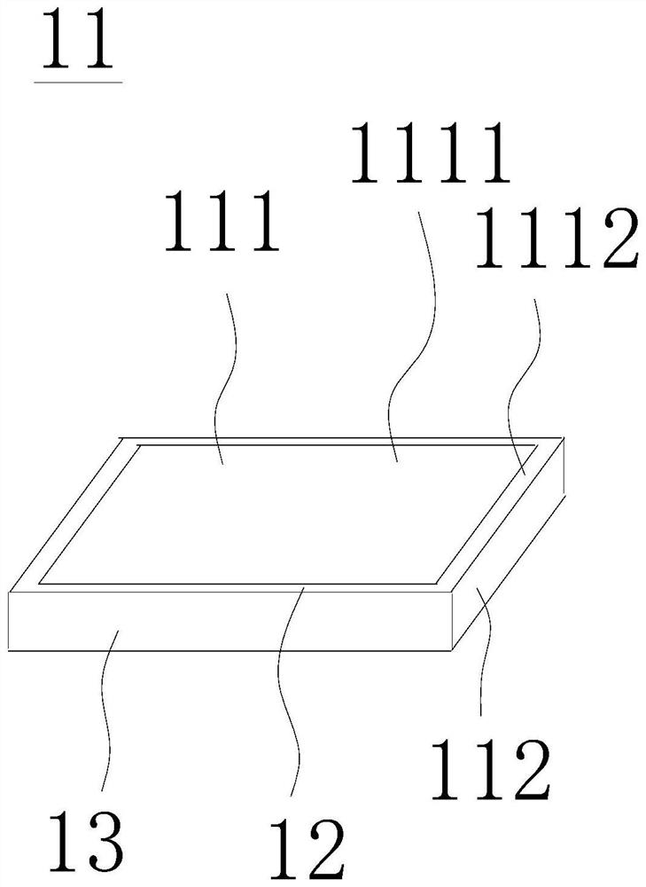
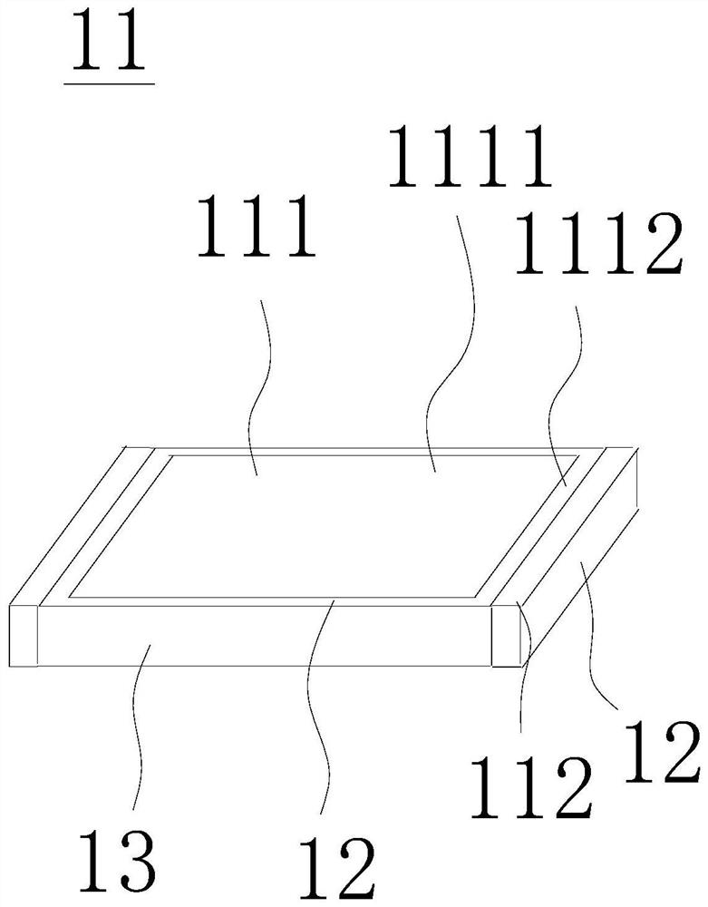
[0022] Please refer to figure 1 and figure 2 shown, figure 1 It is a schematic diagram of an oral scanner according to an embodiment of the present invention, figure 2 It is a schematic diagram of a heater installation area according to an embodiment of the present invention. An oral scanner 100 provided in an embodiment of the present invention is used to scan an object 101. The oral scanner 100 includes a main body 102, a light source 10, an optical element 11, a heater 12, and an imaging unit 16. The main body 102 has a first space 1020 , the light source 10 is disposed in the first space 1020 and is used to emit the first light 1001, the optical element 11 is disposed in the first space 1020 and has a first surface 111, the first surface 111 has a first region 1111 and ...


PUM


Abstract

An oral cavity scanner for scanning an object includes a main body having a first space, a light source disposed in the first space and configured to emit a first light, an image capturing unit disposed in the first space and configured to capture an image of the object, an optical element disposed in the first space and configured to emit a second light, and a heater disposed in the first space. The optical element is arranged in the first space and provided with a first surface, the first surface is provided with a first area and a second area, the heater is arranged in the second area to heat the optical element, the first light rays can reach the object through the first area to form second light rays, and the second light rays reach the image taking unit from the object through the first area. The heater can save power, the optical characteristics and accuracy of the oral cavity scanner are not affected when the demisting efficiency is improved, the heater is not damaged in the cleaning process, and the optical characteristics and accuracy of the oral cavity scanner are not affected.

Description

technical field [0001] The invention relates to an oral scanner, in particular to an oral scanner capable of defogging without affecting optical imaging. Background technique [0002] The front end of the Intra Oral Scanners (IOS) will be equipped with a mirror with an oblique angle, as a function of refracting the projected light to the teeth and refracting the reflected light to the camera inside the IOS for image taking. Because the reflector needs to extend into the mouth, the temperature inside the mouth is higher than the temperature of the outside environment, so the problem of fogging on the reflector surface will occur. [0003] The current common defogging solution is to use a heater to heat and increase the temperature of the mirror surface to achieve the defogging effect. A heater is installed behind the reflector to heat the reflector. The main material of the reflector is glass, which has poor heat conduction effect. The heater is installed on the remote IOS ...

Claims


Application Information

Patent Timeline
Patent Type & Authority Applications(China)
IPC IPC(8): A61B1/253A61B1/05A61B1/06
CPCA61B1/253A61B1/05A61B1/06A61B1/0669A61B1/00096
Inventor 吴柏府李宗熹沈俊明骆怡伶
Owner QISDA OPTRONICS (SUZHOU) CO LTD
Why Eureka
Try Eureka