Novel skin stitching instrument

A suturing device and skin technology, applied in the field of skin suturing devices, can solve the problems of skin damage, secondary wound injury, collapse and other problems of suturing nail wounders, and achieve the effects of avoiding poor wound suturing effect, convenient output, and convenient operation

Pending Publication Date: 2022-03-01
SUZHOU MEIDONG HUICHENG PRECISION COMPONENTS CO LTD
View PDF5 Cites 1 Cited by
  • Summary
  • Abstract
  • Description
  • Claims
  • Application Information

AI Technical Summary

Problems solved by technology

[0004] The purpose of the present invention is to provide a new type of skin stapler to solve the above-mentioned problems in the background technology. However, the existing skin stapler requires the operator to press the handle to staple the staples to the skin, and the operation is time-consuming and laborious. During the process, because the operator sometimes uses too little force, or the staples are not pressed tightly, there will be signs of collapse. When the force is too large, the staples will cause serious damage to the injured skin. At the same time, the staples of the skin stapler The nail outlet will be stuck due to improper force, which will cause the skin stapler to not work normally and cause secondary damage to the wound

Method used


Image

  • Novel skin stitching instrument
  • Novel skin stitching instrument
  • Novel skin stitching instrument

Examples


specific Embodiment 1

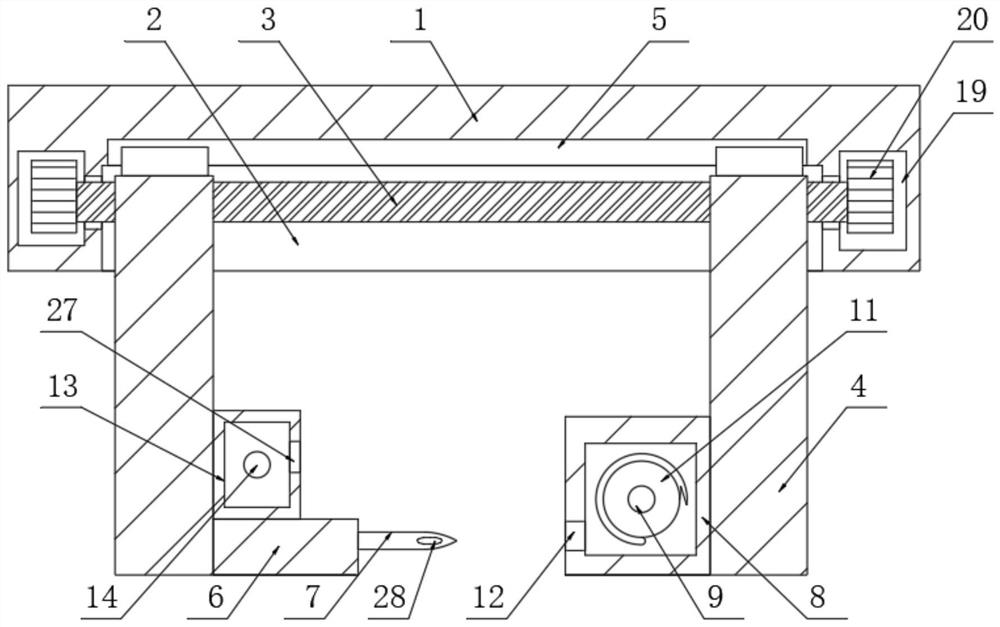
[0028] like figure 2 and image 3 As shown, it includes a casing 1, a groove 2 is provided on the left side of the lower surface of the casing 1, and a threaded rod 3 is rotatably connected to the front and rear sides of the inner wall of the groove 2, and the rod wall of the threaded rod 3 is threadedly connected with a moving block 4. The upper side of the inner wall of the groove 2 is provided with a chute 5, the inner wall of the chute 5 is slidably connected with the upper surface of the moving block 4 through the slider, and the front surface of the rear moving block 4 is fixedly connected with a pin Block 6, the front side surface of the pin block 6 is fixedly connected with a needle head 7, the left side surface of the needle head 7 is provided with a wire inlet hole 28, and the rear side surface of the front side moving block 4 is fixedly connected with a pressure shell 8, the pressure shell 8 There is a rotating device inside, the rotating device includes a first r...

specific Embodiment 2

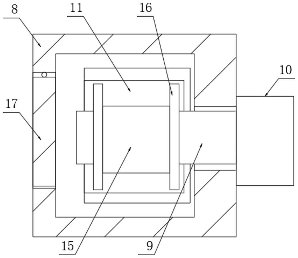
[0030] like image 3 and Figure 4 As shown, the upper surface of the pin block 6 is fixedly connected to the wire harness shell 13, the rear side of the inner wall of the wire harness shell 13 is fixedly connected with a support rod 14, and the rod wall of the support rod 14 and the rod wall of the first rotating rod 9 are sleeved. There is a take-up coil 15, the left and right sides of the take-up coil 15 are fixedly connected with wire baffles 16, the front side surface of the wire harness shell 13 is provided with a wire outlet 27, the left side surface of the pressure shell 8 and the left side surface of the wire harness shell 13 are both. The door body 17 is rotatably connected, and the left side surfaces of the two door bodies 17 are fixedly connected with a lock head 18, which is convenient for replacing the suture thread with a new one. line output.

specific Embodiment 3

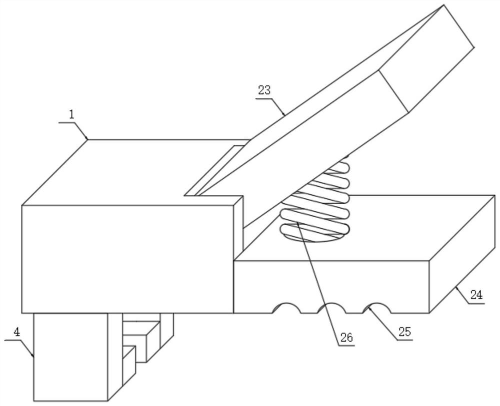
[0032] like Figure 5 and with Image 6 As shown, the front and rear sides of the upper surface of the casing 1 are provided with cavities 19, and the front and rear ends of the threaded rod 3 respectively penetrate the front and rear sides of the inner wall of the groove 2 to the interior of the cavity 19. Both ends are fixedly connected with the first spur gear 20 , the rear side of the inner wall of the casing 1 is rotatably connected with a second rotating rod 21 , and the front and rear ends of the second rotating rod 21 respectively penetrate the front and rear sides of the inner wall of the casing 1 to the cavity 19 Inside, the front and rear ends of the cavity 19 are fixedly connected with the second spur gears 22, the left side surfaces of the two first spur gears 20 and the right side surfaces of the second spur gears 22 are connected through the rack rotation, and the second The rod wall of the rod 21 is fixedly connected with a pressing rod 23, which drives the wh...


PUM


Abstract

The invention discloses a novel skin stitching instrument, and relates to the technical field of skin stitching instruments, the novel skin stitching instrument comprises a shell, the left side of the lower side surface of the shell is provided with a groove, the front side and the rear side of the inner wall of the groove are jointly and rotatably connected with a threaded rod, the rod wall of the threaded rod is in threaded connection with a moving block, and the upper side of the inner wall of the groove is provided with a sliding groove; the inner wall of the sliding groove is slidably connected with the upper side surface of a moving block through a sliding block, the front side surface of the moving block on the rear side is fixedly connected with a needle inserting block, the front side surface of the needle inserting block is fixedly connected with a needle head, the left side surface of the needle head is provided with a wire inlet hole, and the rear side surface of the moving block on the front side is fixedly connected with a pressing shell. In the wound suturing process, secondary damage to a wound caused by a traditional suturing nail is reduced, meanwhile, the difficulty that an operator uses a suturing line for suturing is facilitated, and the wound is sutured more closely.

Description

technical field [0001] The invention relates to the technical field of skin staplers, in particular to a novel skin stapler. Background technique [0002] In human surgery, sutures are routinely used to suture epidermal wounds manually. This suture method requires high suture techniques. In human surgery, sutures are routinely used to suture epidermal wounds manually. The technical requirements are high, the time is long, and the suture depth is completely determined by the operator's operation, which may easily lead to inconsistent suture depths on both sides of the wound, resulting in a certain deviation in the apposition of the two sides of the skin, so that the scar will be wider after the wound heals. , invented a skin stapler for stapling wounds with metal staples. This skin stapler uses a manual method to staple epidermal wounds, which takes less time, and has better stapling depth consistency. The epidermis on both sides of the wound is accurately aligned. After the...

Claims


Application Information

Patent Timeline
Patent Type & Authority Applications(China)
IPC IPC(8): A61B17/04A61B17/06A61B17/08
CPCA61B17/04A61B17/06066A61B17/08A61B2017/081
Inventor 刘子贤刘刚
Owner SUZHOU MEIDONG HUICHENG PRECISION COMPONENTS CO LTD
Why Eureka
Try Eureka