Welding tool for steam turbine partition plate

A welding tool and steam turbine technology, applied in welding equipment, auxiliary welding equipment, welding/cutting auxiliary equipment, etc., can solve the problems of low work efficiency, low efficiency, cumbersome and other problems, achieve convenient operation, convenient cutting, and improve work efficiency Effect

Active Publication Date: 2022-03-01
常州凯度机电有限公司
View PDF8 Cites 0 Cited by
  • Summary
  • Abstract
  • Description
  • Claims
  • Application Information

AI Technical Summary

Problems solved by technology

very inefficient
[0004] At the same time, during the process of the fixture converting inside and outside relative to the baffle unit, the baffle unit not only does not receive the limiting force of the fixture, but also is easily caused by The user applies force to the fixture and touches the partition unit, causing the partition unit to be deflected by external force and affecting product quality
[0005] In view of the related technologies mentioned above, the inventor believes that there are the following defects: 1. In the cutting process, in the process of clamp transposition, not only is loaded down with trivial details, but also easy The partition unit is shifted, which affects the product quality; 2. The clamping process is cumbersome and the work efficiency is low during the cutting and welding process.

Method used


Image

  • Welding tool for steam turbine partition plate
  • Welding tool for steam turbine partition plate
  • Welding tool for steam turbine partition plate

Examples


Embodiment 1

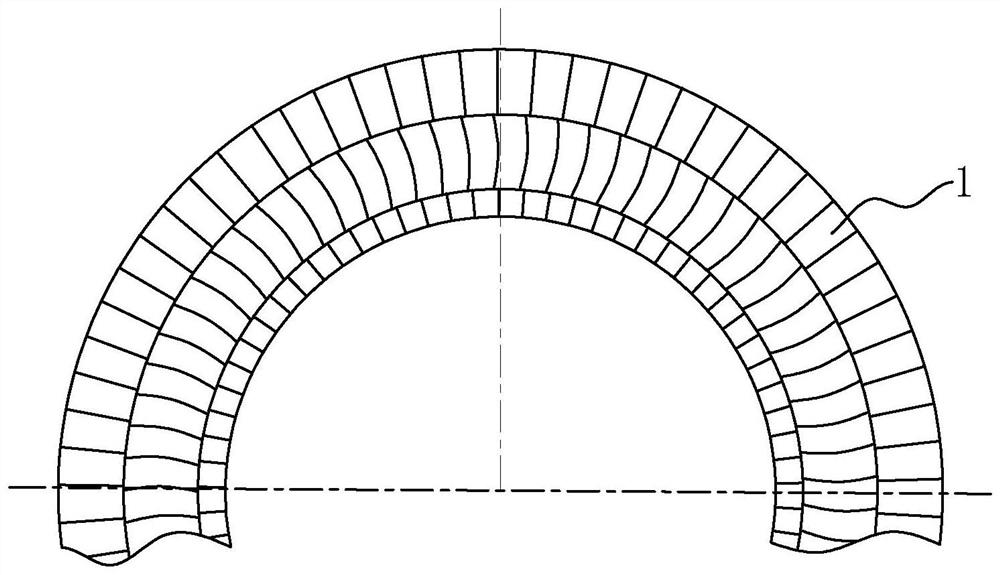
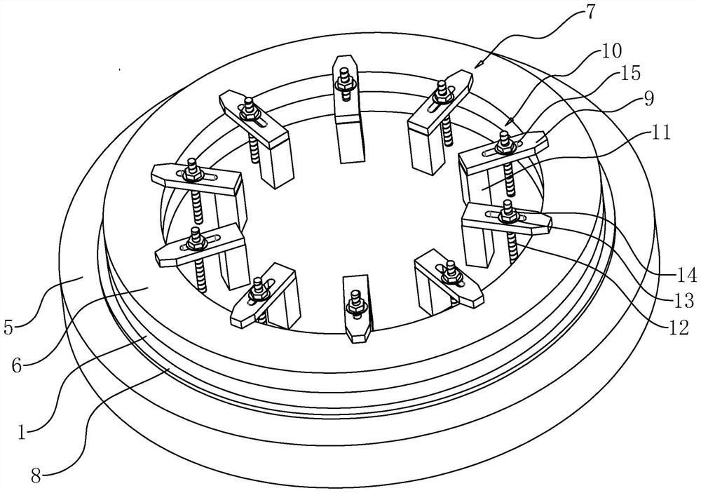
[0049] This application example discloses a welding tool for a steam turbine separator. Refer image 3 A welding tool for a steam turbine separator includes a carpet 5, a pressure ring 6, and a pressure assembly 7. The pressure assembly 7 is provided in a portion of the pressure ring 6 weeks. When the clip is fitted, the pressure ring 6 is paired by the pressure ring 6, and all the separator units 1 to be welded is held by the pressure ring 6 and the carotid 5 to be welded.

[0050] Specific, reference image 3 and Figure 4 The finished member 8 is provided on the fim 5, and the restricted part 8 is annular, and the housing for the separator unit 1 is placed. The pressure assembly 7 includes a straight pressure member 9, a lock member 10, and a support 11. The lock member 10 includes a screw 12 that is sleeve 13 and a thread to which the screw 12 is connected to the screw 12. The screw 12 is disposed in the vertical direction and is fixed to the end surface of the fetal 5. The screw...

Embodiment 2

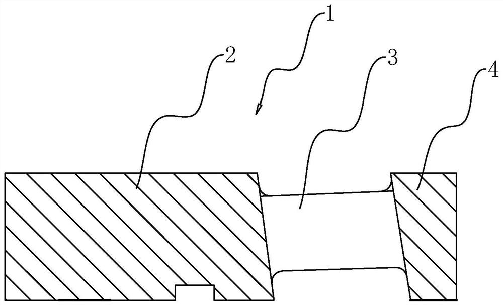
[0060] Refer Figure 7 The difference between Example 2 and Embodiment 1 is that the diameter of the limit piece 8 is smaller than the outer loop diameter of the separator and is greater than the inner ring diameter of the partition. A groove for the fitting site 8 is opened on the separator unit 1.

[0061] At the assembled clip, the groove of the separator unit 1 is aligned with the limit seat member 8 and the groove sleeve is disposed to be placed on the belt 5. Then, all the separator units 1 is placed on the carpet 5 along the limit seat 8 to form a circular separator.

Embodiment 3

[0063] Refer Figure 8 The difference between Example 3 and Embodiment 2 is that the locking member 10 includes a fastener 14 and a screw 12 that is fixed to the upper end of the screw 12, and the tension 14 is a hexagonal prism. The screw 12 is threaded onto the fetal 5. When the clamp is assembled, the screw 12 can be rotated directly to move the elimination head 14 downward, so that the separator unit 1 is fixedly fixed by the diaphragm 6 and the fetal 5.


PUM


Abstract

The welding tool comprises a clamping fixture, a pressing ring and an abutting assembly, the clamping fixture is used for containing a partition plate unit, a limiting piece is arranged on the clamping fixture and used for enabling the partition plate unit to be stably placed on the clamping fixture, and the pressing ring is used for being placed and pressed on the partition plate unit; the abutting assembly comprises a straight pressing piece installed on the clamping fixture and a locking piece used for pressing and locking the straight pressing piece to the pressing ring so that the pressing ring and the clamping fixture can be matched to clamp the partition plate unit. When the partition plate unit needs to be taken down, the locking piece unlocks the direct pressing piece. The straight pressing piece abuts against and is locked on the pressing ring through the locking piece, the pressing ring abuts against and locks the partition plate units, and therefore clamping of all the partition plate units is completed. And a large number of clamps do not need to be clamped one by one, so that the working efficiency is improved.

Description

Technical field [0001] The present application relates to the field of melting pole separator processing, and more particularly to a welding tool for steam turbine separator. Background technique [0002] The partition of the steam turbine is used to secure the static blades and separate the cylinders into a plurality of gas chambers. Refer figure 1 The separator is welded by a plurality of partition units 1 along the circumferential array. Refer figure 2 , The separator unit 1 is fixed by the outer ring 2, the static blades 3, and the plate body 4 are welded. At present, when welding, the separator unit needs to be arranged in turn to form a semi-circle or a whole circle, and then weld it. However, in this process, each separator unit requires a clamp to be fixed, otherwise it is prone to displacement during the welding process, affecting product quality. [0003] And before welding, the inner wall of the separator unit and the outer wall is required. The existing fixture can on...

Claims


Application Information

Patent Timeline
Patent Type & Authority Applications(China)
IPC IPC(8): B23K37/04
CPCB23K37/0443
Inventor 周德钊胡佳宝
Owner 常州凯度机电有限公司
Why Eureka
Try Eureka