Method and device for producing plastic preforms and plastic containers with hot preform reservoirs

A technology for plastic preforms, plastic containers, applied in the field of production and equipment for plastic preforms and plastic containers with thermal preform storage, able to solve the problem of exceeding the process limits, impossible to guarantee the preform inlet temperature Issues such as preform energy content, processing window loss, etc.

Pending Publication Date: 2022-03-01
KRONES AG
View PDF0 Cites 0 Cited by
  • Summary
  • Abstract
  • Description
  • Claims
  • Application Information

AI Technical Summary

Problems solved by technology

[0005] However, the problem with this coupled approach (preform production incorporated into the filling operation) is that due to the limited control process of IR linear oven technology, it is necessary to ensure a uniformity of + / - 1°C between successive preforms. Preform inlet temperature, and fluctuations greater than + / - 5°C over an extended period of time (daily fluctuations) can lead to loss of processing window
Therefore, it is almost impossible to use the first heat of injection molding (60°C) because even the slight pauses (<5 minutes) that often occur in the filling line cannot be compensated, and the temperature of the preform drops too much, beyond process limit
[0006] If such a standstill occurs, for example, the preforms cool over time on the non-tempering conveyor section between the injection molding machine and the heating device located before the blow molding machine, and it is impossible to guarantee a uniform preform inlet temperature or Necessary preform energy content in the heating unit

Method used


Image

  • Method and device for producing plastic preforms and plastic containers with hot preform reservoirs
  • Method and device for producing plastic preforms and plastic containers with hot preform reservoirs

Examples


Embodiment Construction

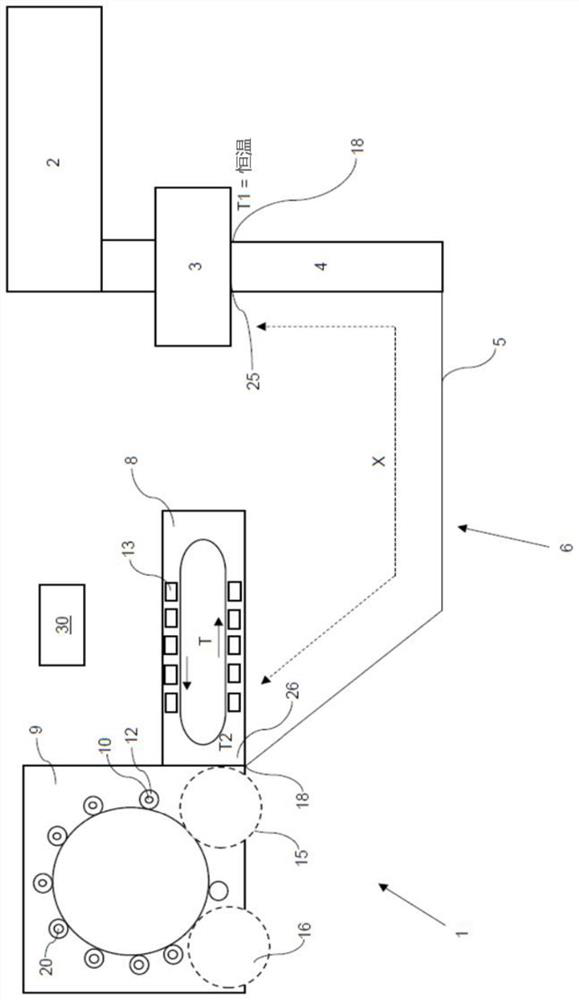
[0054] figure 1 A schematic diagram of the apparatus 1 producing the plastic preform 10 and the plastic container 20 according to the present invention is shown. Reference numeral 2 refers to an injection molding machine producing a plastic preform 10. After production, the plastic preform is transferred to the thermal preform reservoir 3 and maintains a constant temperature T1 here, which corresponds to the temperature of the plastic preform from the injection molding machine 2.

[0055] For example, if the subsequent machine has been downtime, the plastic preform can preferably prevent further delivery of the outlet 25 of the thermal preform storage 3 by the blocking device 18. Otherwise, the plastic preform is passed through the preform reservoir 3 in a predetermined time, and then into the sorting device 4, the sorting device 4 is sorted in a predetermined manner, in particular, in the same manner. Before the plastic preform is fed to the heating device 8 along the conveying ...


PUM


Abstract

The invention relates to a method for operating a plant for producing plastic preforms and plastic containers, comprising at least one injection molding machine and a blow molding machine, in which the plastic preforms are injection-molded, in which the plastic containers are formed, and from which the plastic preforms are fed to the blow molding machine, a heating device is arranged downstream of the injection molding machine, and the injection molding machine is connected with the blow molding machine. According to the invention, the plastic preforms produced in the injection molding machine are transferred directly after production to a hot preform reservoir, which holds the plastic preforms at a predetermined temperature, the speed and / or a parameter of at least one subsequent processing device being variable.

Description

Technical field [0001] The present invention relates to a method of producing a device of a plastic preform and a plastic container and a device for producing plastic preforms and plastic containers. Background technique [0002] Such equipment and methods have long known in the prior art. From the applicant's internal prior art, the plastic preform is first produced by an injection molding process, and then temporarily stored in the form of a bulk material until further processing is further processed. For further processing, the preform is then sent to a preform sorting device as a bulk material, and the heating device and subsequent blow molding machine are sent in an ordered form, and the plastic preform is formed into a plastic container. [0003] The above two-step tensile blow molding process is characterized in that the preform production process and the stretch blow mold or the molding process are separated from each other. However, the disadvantage is that the first ste...

Claims


Application Information

Patent Timeline
Patent Type & Authority Applications(China)
IPC IPC(8): B29C49/06B29C49/64B29C49/42B29C49/78
CPCB29C49/061B29C49/6418B29C49/4205B29C49/78B29C49/786B29L2031/712B29C49/02B29C2049/023B29C49/06B29C49/12B29C49/46B29C2049/4697B29K2067/003B29L2031/7158B29C49/6409B29C2949/0715Y02P70/10B29C49/36B29C2049/4638B29K2105/253
Inventor H·约亨
Owner KRONES AG
Why Eureka
Try Eureka