Suspension type unmanned aerial vehicle carrying device

A suspension and suspension technology, which is applied in the field of suspended UAV loading devices, can solve the problems of UAV shaking and instability, difficult and cumbersome unloading, accidental falling, etc. Safety, Enhanced Adaptability Effects

Pending Publication Date: 2022-03-01
HANGZHOU POLYTECHNIC
View PDF0 Cites 0 Cited by
  • Summary
  • Abstract
  • Description
  • Claims
  • Application Information

AI Technical Summary

Problems solved by technology

[0003] The existing UAV loading device exists: it is bound to the UAV support by a rope, which makes unloading difficult and cumbersome, and it is easy to accidentally pull the UAV when unloading the rope manually, causing the UAV to shake and become unstable. In the event of an accidental fall

Method used


Image

  • Suspension type unmanned aerial vehicle carrying device
  • Suspension type unmanned aerial vehicle carrying device
  • Suspension type unmanned aerial vehicle carrying device

Examples


Embodiment 1

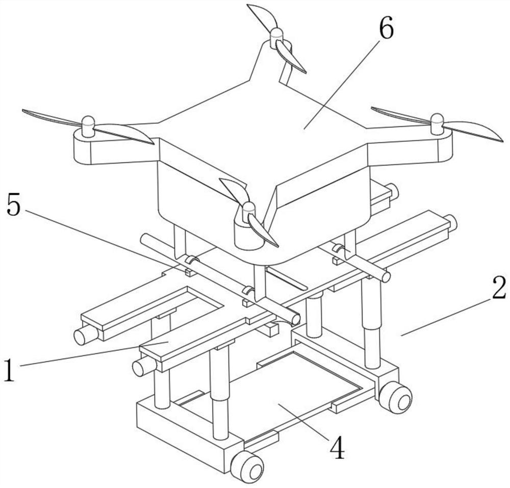
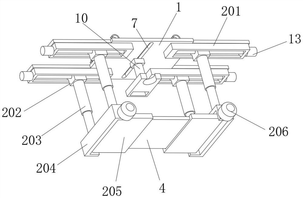
[0027] see Figure 1-4 , in the embodiment of the present invention, the rotary unloading mechanism 2 includes a carriage 201 fixedly installed at the bottom end of the suspension support plate 1, the inside of the carriage 201 is slidably connected with a slider 202, and the outside of the carriage 201 is fixedly installed with a drive socket The ball screw inside the slider 202 rotates the second motor 13, the bottom end of the slider 202 is fixedly equipped with a first hydraulic rod 203, and the bottom end of the first hydraulic rod 203 is fixedly installed with a support seat 204, and the support seat 204 The inside of the support plate 205 is connected with the support plate 205 through the rotation of the rotating shaft. The first motor 206 that drives the support plate 205 to rotate is fixedly installed on the outside of the support seat 204. The inside of the support plate 205 is provided with a groove 3, and the inside of the groove 3 is flexibly connected The connec...

Embodiment 2

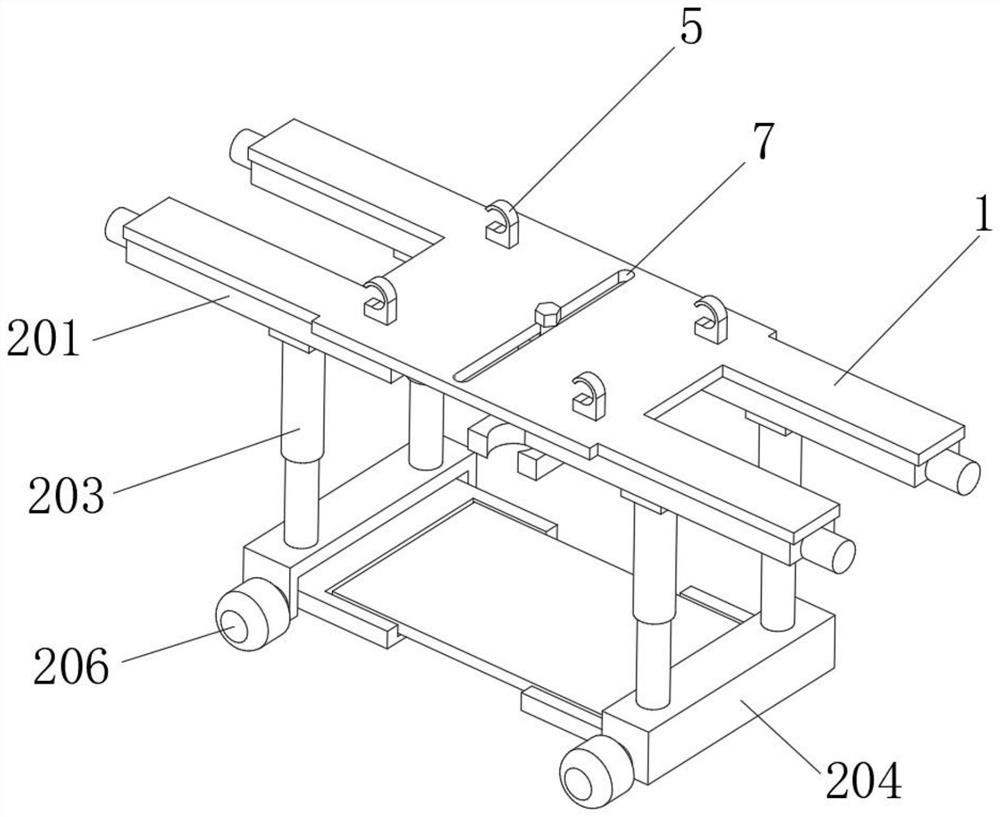
[0029] see Figure 4-5 , the inside of the suspension support plate 1 is provided with a chute 7, the inside of the chute 7 is slidingly connected to the limit fixing bolt 8, the bottom end of the limit fixing bolt 8 is threadedly connected with the adjustment block 9, and the bottom end of the adjustment block 9 is fixedly installed There is a second hydraulic rod 10, and the bottom end of the second hydraulic rod 10 is fixedly equipped with an extruding plate 11, and the inside of the extruding plate 11 is provided with different shapes of limiting grooves 12 for stabilizing the sharp part of the top of the article. The groove 7 can control the adjustment block 9 to move and rotate horizontally, and the adjustment block 9 can drive the extrusion plate 11 to adjust the position, so as to ensure that the extrusion plate 11 can fall stably to squeeze and fix the article. By setting the second hydraulic rod 10, It can control the lifting of the extrusion plate 11, so that the ex...


PUM


Abstract

The suspension type unmanned aerial vehicle loading device comprises a suspension supporting plate, a rotary unloading mechanism capable of improving unloading convenience is arranged at the bottom end of the suspension supporting plate, the rotary unloading mechanism comprises a sliding frame fixedly installed at the bottom end of the suspension supporting plate, and a sliding block is slidably connected into the sliding frame; and a first hydraulic rod is fixedly installed at the bottom end of the sliding block, a supporting seat is fixedly installed at the bottom end of the first hydraulic rod, a supporting plate is rotationally connected to the interior of the supporting seat through a rotating shaft, and a first motor for driving the supporting plate to rotate is fixedly installed on the outer side of the supporting seat. By arranging the rotary unloading mechanism, compared with an existing mode that a carrying device is bound to an unmanned aerial vehicle support through a rope, the unmanned aerial vehicle can unload more conveniently and quickly, and the situation that the unmanned aerial vehicle shakes and falls accidentally due to the fact that the unmanned aerial vehicle is pulled when the binding rope is released during manual unloading can be avoided; and the safety of the unmanned aerial vehicle during unloading is improved.

Description

technical field [0001] The invention relates to the technical field of unmanned aerial vehicle equipment, in particular to a suspended unmanned aerial vehicle equipment. Background technique [0002] Unmanned aircraft, referred to as "unmanned aerial vehicle", is an unmanned aircraft controlled by radio remote control equipment and self-contained program control device, or is completely or intermittently operated autonomously by the on-board computer. Compared with manned aircraft, UAVs are often more suitable for tasks that are too "dull, dirty or dangerous". UAVs can be divided into military and civilian use according to the application field. For military use, UAVs are divided into reconnaissance aircraft and target aircraft. UAV + industry application is the real rigid demand of UAV; in aerial photography, agriculture, plant protection, micro selfie, express transportation, disaster rescue, observation of wild animals, monitoring of infectious diseases, surveying and map...

Claims


Application Information

Patent Timeline
IPC IPC(8): B64D9/00B64C39/02
CPCB64D9/003B64C39/02B64U2101/60
Inventor 黄煜栋
Owner HANGZHOU POLYTECHNIC
Why Eureka
Try Eureka