Movable multi-track fork and working method thereof

A multi-track and turnout technology, applied in the field of subway tunnel construction, can solve the problems of dismantling and splicing the track for a long time, affecting construction efficiency and construction progress, and taking a long time to reach the working face, etc., achieving significant social and economic benefits , shorten the excavation period and save construction investment

Pending Publication Date: 2022-03-01
CHINA RAILWAY SHANGHAI ENGINEERING BUREAU GROUP CO LTD
View PDF0 Cites 2 Cited by
  • Summary
  • Abstract
  • Description
  • Claims
  • Application Information

AI Technical Summary

Problems solved by technology

[0002] The turnout is a staggering device used for the entry and exit of multiple trains of rail transport vehicles for muck transportation during tunnel construction. At present, it is mainly in the form of fixed turnouts, and most of them are located at the platform or tunnel entrance. When the tunnel is constructed over a long distance, the fixed The turnout is far away from the excavation work face, and it takes a long time for the rail transport vehicle driving out to reach the fixed turnout position, and it will take a long time to arrive at the wrong vehicle after passing the incoming rail transport vehicle. On the working face, during the period of driving in and out, the excavation of the muck work of the tunnel must be stopped, which seriously affects the construction efficiency and construction progress.
[0003] Even if the distance between the fixed turnout and the tunnel working face is adjusted in time during construction, the work of dismantling and splicing the track will waste a long time, seriously affecting the progress of the construction period. This is a common problem in excavating tunnels by rail trains

Method used


Image

  • Movable multi-track fork and working method thereof
  • Movable multi-track fork and working method thereof
  • Movable multi-track fork and working method thereof

Examples


Embodiment

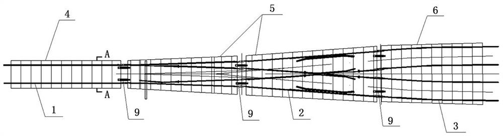
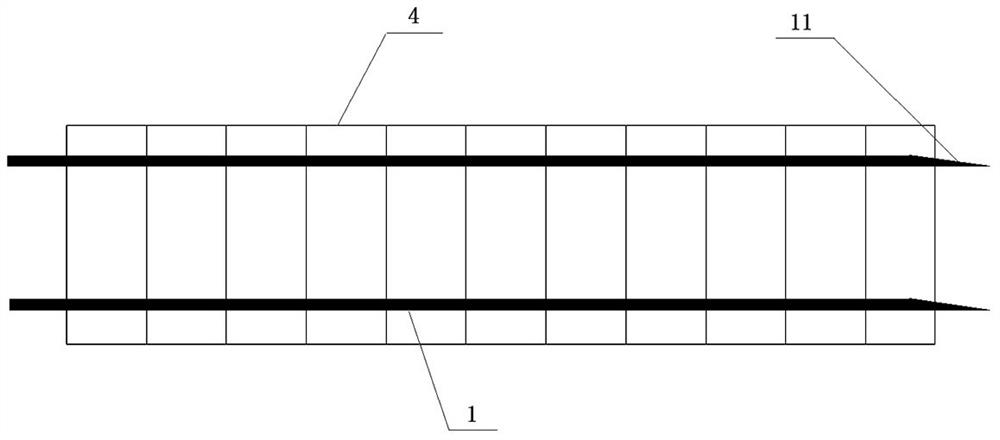
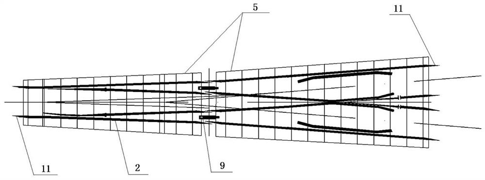
[0027] Example: such as Figure 1-8 As shown, this embodiment relates to a movable multi-track turnout, which mainly includes a front-end guide rail 1, a turnout 2, and a rear-end guide rail 3 arranged in sequence. The front-end guide rail 1 is fixed on the first wear-resistant steel plate 4 through a spring clip, and the turnout 2 is fixed on the second wear-resistant steel plate 5 by a spring clamp, the rear guide rail 3 is fixed on the third wear-resistant steel plate 6 by a spring clamp, and the first wear-resistant steel plate 4, the second wear-resistant steel plate 5 and the third wear-resistant steel plate 6 are all installed on the tunnel track 7. Among them, the turnout 2 is designed in sections, and is formed by the first turnout assembly and the second turnout assembly. The first turnout assembly and the second turnout assembly are installed on two second wear-resistant steel plates 5 respectively; The end guide rail and the second rear end guide rail, the first r...


PUM


Abstract

The movable multi-track turnout comprises a front-end guide rail, a turnout and a rear-end guide rail which are arranged in sequence, and the front-end guide rail, the turnout and the rear-end guide rail are installed on a first wear-resisting steel plate, a second wear-resisting steel plate and a third wear-resisting steel plate correspondingly. The first wear-resistant steel plate, the second wear-resistant steel plate and the third wear-resistant steel plate are all mounted on a tunnel track; guide rollers are arranged at the bottoms of the first wear-resistant steel plate, the second wear-resistant steel plate and the third wear-resistant steel plate, and the guide rollers and the tunnel track are arranged in a relative rolling manner; the first wear-resistant steel plate and the second wear-resistant steel plate as well as the second wear-resistant steel plate and the third wear-resistant steel plate are connected through hinge connectors; the front end of the front-end guide rail and the rear end of the rear-end guide rail are each of a slope structure, the wedge-shaped structure of the rear end of the front-end guide rail is attached to the wedge-shaped structure of the front end of the turnout, and the wedge-shaped structure of the front end of the rear-end guide rail is attached to the wedge-shaped structure of the rear end of the turnout. The method has the advantage that the problem of wrong rail transport vehicles in the long-distance tunnel can be solved.

Description

technical field [0001] The invention relates to the technical field of subway tunnel construction, in particular to a movable multi-track switch and a working method thereof. Background technique [0002] The turnout is a staggering device used for the entry and exit of multiple trains of rail transport vehicles for muck transportation during tunnel construction. At present, it is mainly in the form of fixed turnouts, and most of them are located at the platform or tunnel entrance. When the tunnel is constructed over a long distance, the fixed The turnout is far away from the excavation work face, and it takes a long time for the rail transport vehicle driving out to reach the fixed turnout position, and it will take a long time to arrive at the wrong vehicle after passing the incoming rail transport vehicle. On the working face, during the period of driving in and out, the excavation work of the muck work of the tunnel must be stopped, which seriously affects the constructi...

Claims


Application Information

Patent Timeline
Patent Type & Authority Applications(China)
IPC IPC(8): E01B23/06E01B23/04E01B23/00
CPCE01B23/06E01B23/04E01B23/00
Inventor 李想文毅然唐虎陆跃程桂芝陶路路汪光继姜宇恒曹艳荣
Owner CHINA RAILWAY SHANGHAI ENGINEERING BUREAU GROUP CO LTD
Why Eureka
Try Eureka