Rock ground underground structure bottom plate structure and building method thereof

A technology for underground structures and rock foundations, applied in underwater structures, foundation structure engineering, foundation structure tests, etc., can solve problems such as single construction and connection structures, decline in construction quality, and reduced service life, so as to ensure stable sedimentation , reduce the impact, improve the effect of service life

Pending Publication Date: 2022-03-01
上海市建工设计研究总院有限公司
View PDF4 Cites 0 Cited by
  • Summary
  • Abstract
  • Description
  • Claims
  • Application Information

AI Technical Summary

Problems solved by technology

[0004] The object of the present invention is to provide a bottom plate structure of a rocky foundation underground structure and a construction method thereof, so as to solve the existing bottom plate structure of a rocky foundation underground structure proposed in the above-mentioned background technology. During the construction process, its construction and connection structure are single, Problems that lead to a decrease in build quality and reduced service life

Method used


Image

  • Rock ground underground structure bottom plate structure and building method thereof
  • Rock ground underground structure bottom plate structure and building method thereof
  • Rock ground underground structure bottom plate structure and building method thereof

Examples


Embodiment Construction

[0032] The following will clearly and completely describe the technical solutions in the embodiments of the present invention with reference to the accompanying drawings in the embodiments of the present invention. Obviously, the described embodiments are only some, not all, embodiments of the present invention.

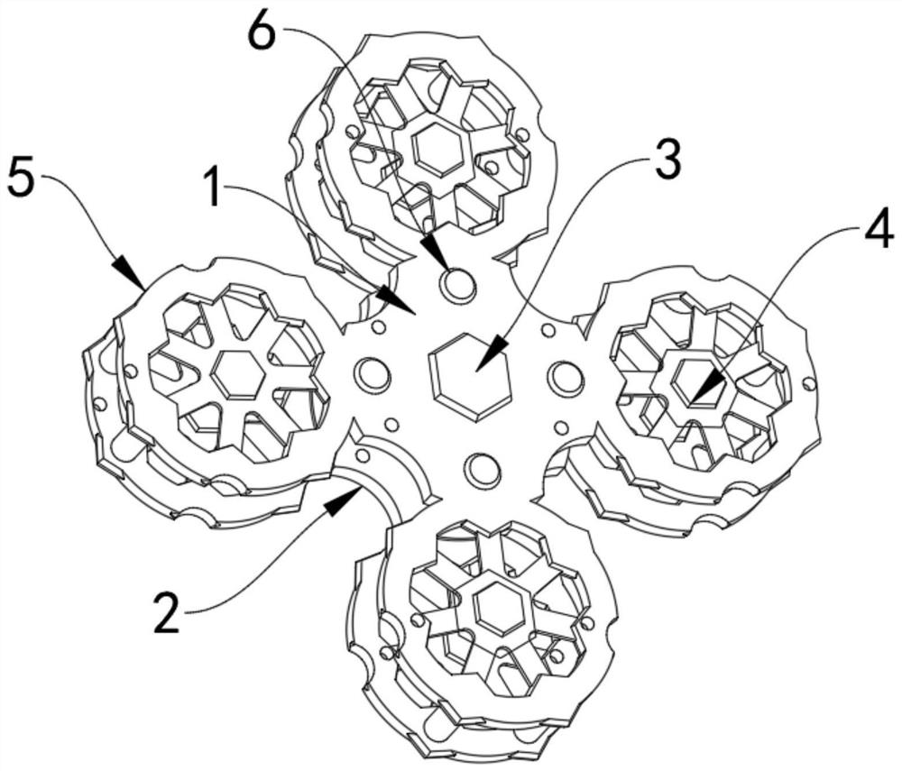
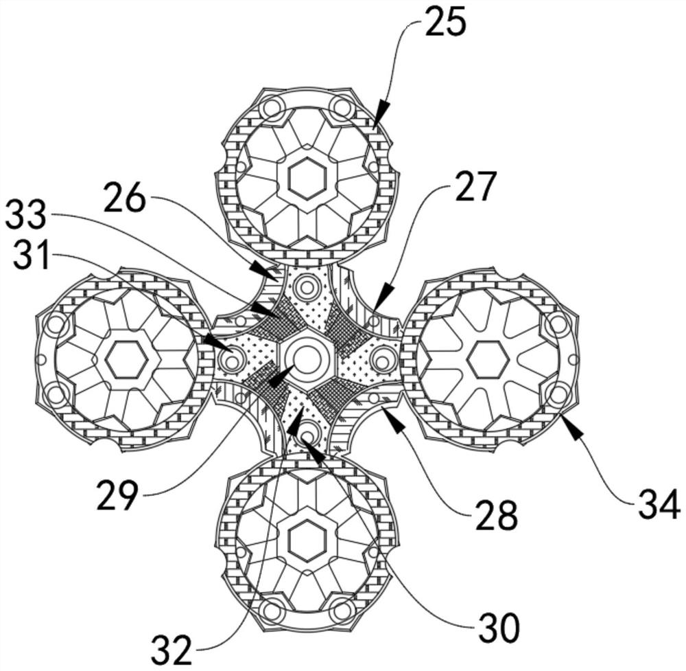
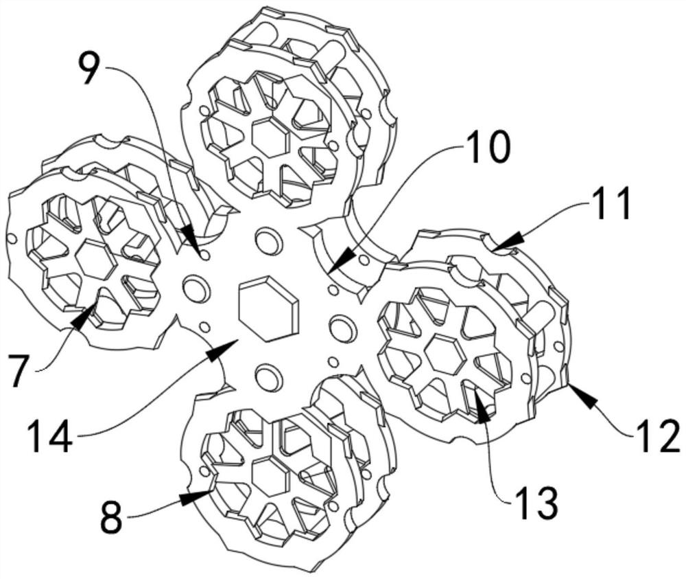
[0033] see Figure 1-7 , an embodiment provided by the present invention: a bottom plate structure of an underground structure of a rocky foundation, comprising an upper frame center plate 1, a lower frame center plate 2 is arranged below the upper frame center plate 1, and a lower frame is arranged below the upper frame center plate 1 The outer ends of the center plate 2 are provided with ring-shaped carriers 5, and the middle of the upper center plate 1 is provided with a supporting pillar detection end 3. The pillar end 4 is provided with a central damping column 18 at the lower end of the upper center plate 1 , and the outer end of the split pillar end 4 is provi...


PUM


Abstract

The invention discloses a bottom plate structure of a rock foundation substructure and a building method of the bottom plate structure, relates to the technical field of rock foundation engineering, and aims to solve the problems that the building quality is reduced and the service life is shortened due to the fact that a building and connecting structure of an existing bottom plate structure of the rock foundation substructure is single in the building process. A lower frame center plate is arranged below the upper frame center plate, annular carrying frames are arranged at the outer ends of the upper frame center plate and the lower frame center plate below the upper frame center plate, a supporting column bearing detection end is arranged in the middle of the upper frame center plate, and a reinforcing column is arranged on the outer side of the supporting column bearing detection end. A split supporting column end is arranged in the middle of the annular carrying frame, a center damping column is arranged at the lower end of the upper frame center plate, a connecting clamping plate is arranged at the outer end of the split supporting column end, a damping rubber layer is arranged on the outer wall of the upper frame center plate, and the damping rubber layer and the upper frame center plate are integrally formed. Four first butt joint clamping grooves are formed in the outer end of the upper frame center plate.

Description

technical field [0001] The invention relates to the field of rock foundation engineering processing, in particular to a rock foundation underground structure floor structure and a construction method thereof. Background technique [0002] Rock foundation, the rock mass under the foundation of the building to bear the load of the building. For hydraulic structures such as dams and sluices, the deformation, anti-sliding stability, bearing capacity, and seepage stability of the rock foundation must meet Certain safety requirements are required to ensure the normal operation of the building. For complex foundations, when the bearing capacity is insufficient or the anti-sliding stability is poor, the rock foundation needs to be reinforced. The principles and methods of the treatment can be found in Rock Foundation Treatment According to different construction conditions, the underground structure of the rock foundation is built differently. [0003] During the construction proc...

Claims


Application Information

Patent Timeline
Patent Type & Authority Applications(China)
IPC IPC(8): E02D3/00E02D3/12E02D29/045E02D31/08E02D33/00
CPCE02D3/00E02D3/12E02D29/045E02D31/08E02D33/00E02D3/005
Inventor 刘玖壮韩建勇
Owner 上海市建工设计研究总院有限公司
Why Eureka
Try Eureka