Construction process of novel counterfort retaining wall

A construction technology, buttress-type technology, which is applied in the field of construction technology of new buttress-type retaining walls, can solve the problems of wasteful masonry and large floor space

Active Publication Date: 2022-03-01
SHUOHUANG RAILWAY DEV +1
View PDF6 Cites 2 Cited by
  • Summary
  • Abstract
  • Description
  • Claims
  • Application Information

AI Technical Summary

Problems solved by technology

However, there is a waste of masonry and it occupies a large area, and new land needs to be requisitioned during the implementation process.

Method used


Image

  • Construction process of novel counterfort retaining wall
  • Construction process of novel counterfort retaining wall
  • Construction process of novel counterfort retaining wall

Examples


Embodiment 1

[0052] Example 1, in the design of the rail material platform for large and medium repair projects, considering that the existing rail material platform is generally filled relatively high, basically brick retaining walls are used to close the slope, and the walls generally have bulging and cracking diseases, which affect It is safe to use, so the present invention proposes the rationalization improvement of adopting the buttress-type retaining wall to close the slope and make the rail material platform. The buttress-type retaining wall is a light-weight retaining structure. Compared with the traditional gravity-type retaining wall, it not only saves masonry but also occupies a small area, and does not require new land acquisition during the implementation process. After the present invention was tested, the two newly-built rail material platforms of Suning North Railway Station were safe and stable, well used, and had good popularization value.

[0053] Specific implementatio...

Embodiment 2

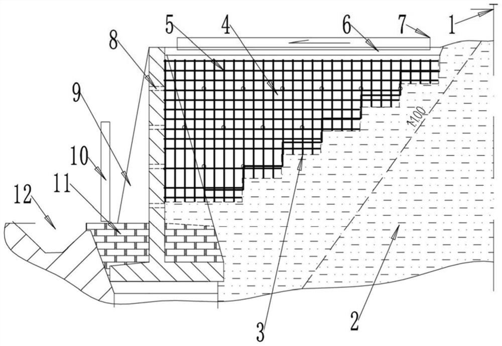
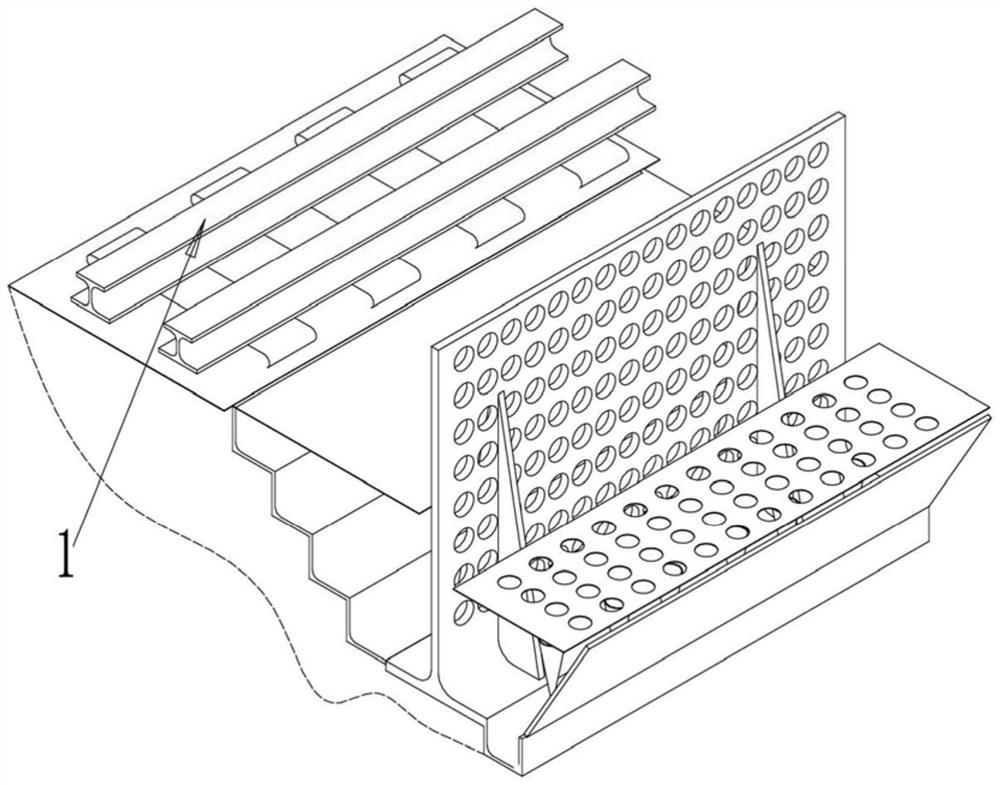
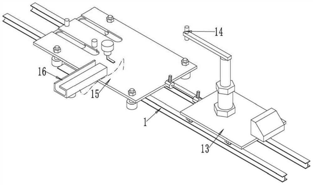
[0055] Example 2, such as Figure 1-7 As shown, the buttress-type retaining wall used for the rail material platform in this embodiment is arranged on the concrete retaining wall toe 3 on both sides of the existing road shoulder 2 of the rail member 1, which is a stepped structure;

[0056] Ditch the outer bottom of the toe 3 of the concrete retaining wall and place the bottom of the buttress 9; fill and compact the gravel soil layer 11 on the bottom upper surface and bottom of the buttress 9;

[0057] A backfill earth-stone layer 4 is placed between the vertical wall of the buttress 9 and the toe 3 of the concrete retaining wall; drain holes 8 are respectively arranged on the backfill earth-rock layer 4 and the vertical wall of the buttress 9;

[0058] In the backfill earth-stone layer 4, a steel bar assembly 5 in the wall is arranged and overlapped with the steel bar of the buttress 9;

[0059] A concrete hardening surface 6 is arranged on the backfill earth-rock layer 4, a...


PUM


Abstract

The invention relates to a construction process of a novel counterfort retaining wall, which is arranged at concrete retaining wall toes on two side parts of an existing road shoulder of a steel rail piece, and is of a stepped structure. Ditching at the bottom of the outer side of the toe of the concrete retaining wall and placing the bottom of the buttress; gravel soil layers are filled and tamped on the upper surfaces and the bottoms of the bottoms of the buttress pieces; a backfill earth-rock layer is placed between the vertical wall of the buttress piece and the toe of the concrete retaining wall; drain holes are respectively formed in the backfill soil and stone layer and the vertical wall of the buttress piece; a reinforcing steel bar assembly in the wall body is arranged in the backfill soil and stone layer and is in lap joint with reinforcing steel bars of the buttress pieces; the device is reasonable in design, compact in structure and convenient to use.

Description

technical field [0001] The invention relates to a construction technology of a novel buttress type retaining wall, in particular to a mechanized construction technology. Background technique [0002] The commonly used embankment retaining structure in railway engineering is gravity retaining wall, which has simple structure, convenient construction and relatively low cost. However, when the height of the gravity retaining wall is high, the requirements for the bearing capacity of the foundation are relatively high, and the section is also large. Another type of retaining structure is the buttress-type retaining wall. The toe plate of the buttress-type retaining wall can significantly increase the anti-overturning stability of the retaining wall and reduce the stress of the base. The tenon can increase the anti-skid performance of the structure. The buttress retaining wall is a light retaining structure with simple structure, convenient construction, small wall section and l...

Claims


Application Information

Patent Timeline
IPC IPC(8): E02D29/02E02D3/10E02D15/00
CPCE02D29/02E02D29/0275E02D3/10E02D15/00
Inventor 王敬白新荣牛增建王冬立陈树礼
Owner SHUOHUANG RAILWAY DEV
Why Eureka
Try Eureka