
Harmonic reducer and robot

A technology of harmonic reducer and input shaft, which is applied in the direction of manipulators, mechanical equipment, program control manipulators, etc. It can solve the problem that the small diameter of the hollow hole cannot meet the needs of a large number of cables, and achieve the effect of compact bearing structure

Pending Publication Date: 2022-03-01
GREE ELECTRIC APPLIANCES INC OF ZHUHAI
View PDF0 Cites 0 Cited by
  • Summary
  • Abstract
  • Description
  • Claims
  • Application Information

AI Technical Summary

Problems solved by technology

[0004] Therefore, the present invention provides a harmonic reducer and a robot, which can overcome the disadvantages in the related art that the wave generator of the harmonic reducer has a smaller hollow hole diameter and cannot meet the routing requirements of a large number of cables.

Method used


Image

  • Harmonic reducer and robot
  • Harmonic reducer and robot
  • Harmonic reducer and robot

Examples


Embodiment Construction

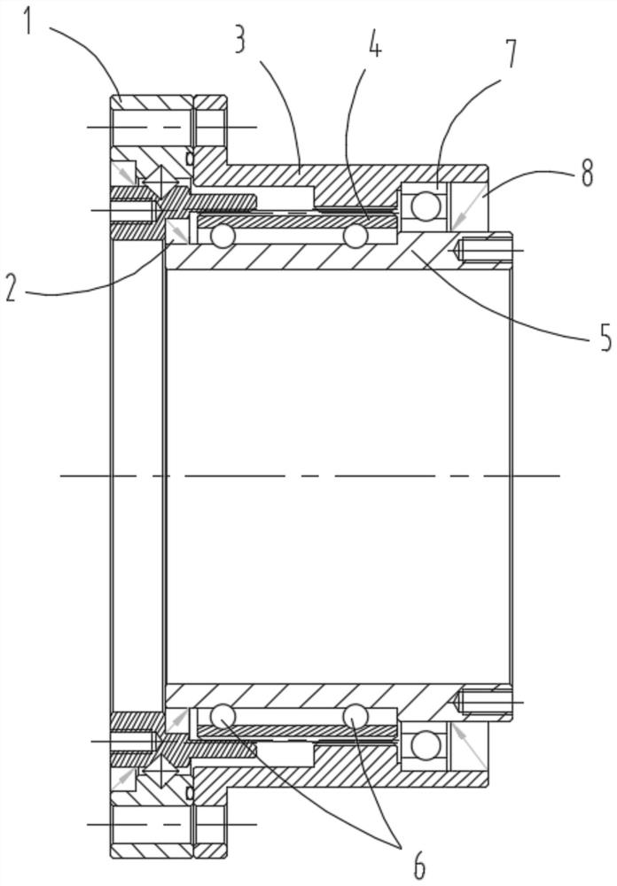
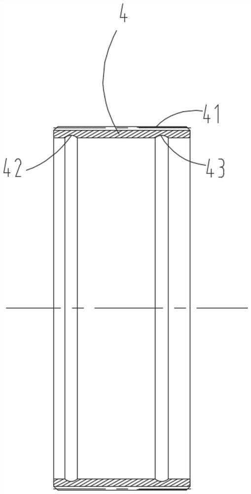
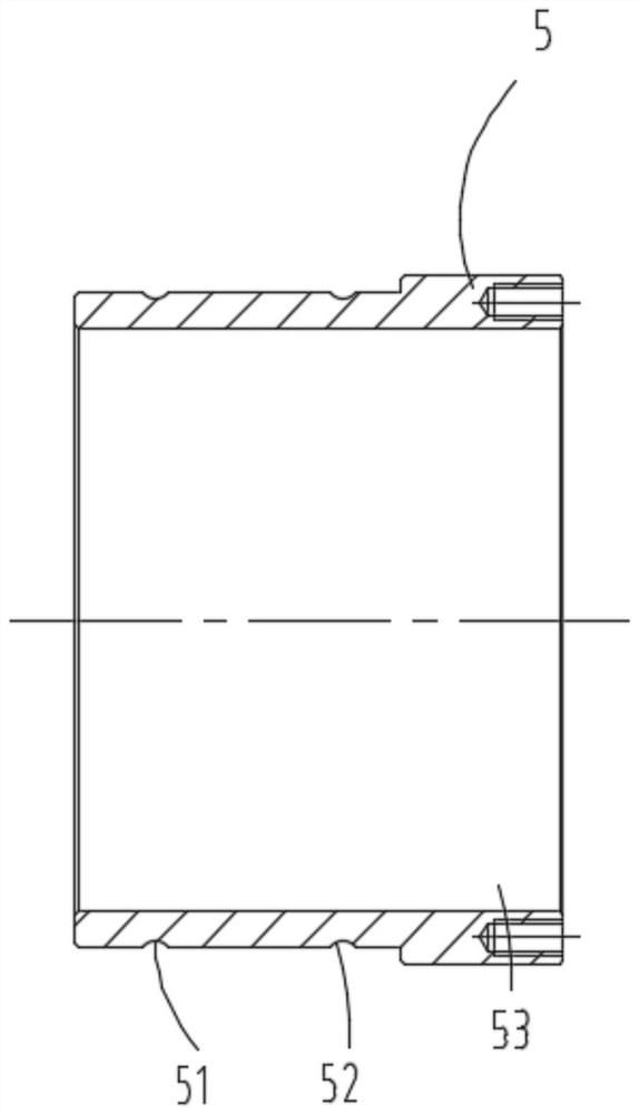
[0021] see in conjunction Figure 1 to Figure 5 As shown, according to the embodiment of the present invention, a harmonic reducer is provided, including an input shaft 5 and a flex spline 4, the input shaft 5 has a hollow hole 53 passing through both axial ends thereof, the input shaft 5 and the The flexible spline 4 is set and a gap is formed between the two. A first raceway 52 is provided on the outside of the shaft wall of the input shaft 5, and a second roller is provided on the side of the flexspline 4 facing the input shaft 5. The track 43, the ball 6 is arranged between the first track 52 and the second track 43. In this technical solution, the outer ring and the inner ring of the bearing between the input shaft and the flexspline in the traditional harmonic reducer are respectively integrated with the flexspline 4 and the input shaft 5 to replace it, so that the bearing structure is compact, Furthermore, the diameter of the hollow hole 53 of the input shaft 5 can be ...


PUM


Abstract

The harmonic reducer comprises an input shaft and a flexible gear, the input shaft is provided with a hollow hole penetrating through the two axial ends of the input shaft, the input shaft and the flexible gear are sleeved, a gap is formed between the input shaft and the flexible gear, a first roller path is arranged on the outer side of the shaft wall of the input shaft, and a second roller path is arranged on the outer side of the shaft wall of the input shaft. A second roller path is arranged on the side, facing the input shaft, of the flexible gear, and balls are arranged between the first roller path and the second roller path. According to the harmonic reducer, the outer ring and the inner ring of the bearing located between the input shaft and the flexible gear in a traditional harmonic reducer are integrated with the flexible gear and the input shaft to replace the bearing, so that the bearing is compact in structure, and the diameter of a hollow hole of the input shaft can be designed to be larger on the premise that the outer diameter of the harmonic reducer is fixed; and application scenes of more cable penetration can be satisfied.

Description

technical field [0001] The invention belongs to the technical field of reducer manufacturing and design, and in particular relates to a harmonic reducer and a robot. Background technique [0002] The harmonic reducer has many advantages such as high transmission precision, large speed ratio, small size, simple structure and wide application. The reducer mainly consists of three basic components, rigid wheel, flexible wheel and wave generator. The working process is generally that the rigid spline is fixed, and when the wave generator rotates, the flexible spline is forced to produce elastic deformation, so that the teeth of the flexible spline and the rigid spline enter the meshing state, thereby realizing the transmission. [0003] The traditional harmonic reducer needs to assemble the bearing between the flexible wheel and the input shaft. The setting of the bearing forms a limit on the hollow hole diameter of the input shaft. Often small, the ratio of the hole diameter ...

Claims


Application Information

Patent Timeline
IPC IPC(8): F16H49/00F16H55/08F16H55/17F16H57/02F16C33/58B25J9/10
CPCF16H49/001F16H55/0833F16H57/0018F16C33/581B25J9/1025F16H2055/176F16H2057/02039
Inventor 谷甲甲程中甫张皓杨繁荣袁成林张亚超
Owner GREE ELECTRIC APPLIANCES INC OF ZHUHAI
Learn More