Cooling structure for head of flame tube of combustion chamber of medium-thrust aero-engine

A technology for the head of a flame tube and an aero-engine, which is applied in the direction of a combustion chamber, a continuous combustion chamber, and a combustion method. The effect of increasing the coverage area and reducing the gas volume

Active Publication Date: 2022-03-01
中国航发贵阳发动机设计研究所
View PDF8 Cites 2 Cited by
  • Summary
  • Abstract
  • Description
  • Claims
  • Application Information

AI Technical Summary

Problems solved by technology

[0004] At present, the cooling method of orifice plate + baffle plate is often used for the head of the combustion chamber, but because of the complex flow field structure of the head of the flame tube, it is easy to appear the situation of vortex zone and so on.
In addition, with the development of combustion chamber technology, the cooling air volume of the flame tube will gradually decrease, and the cooling air volume of the head of the flame tube will also decrease accordingly. Therefore, an efficient cooling structure must be adopted for the head of the flame tube; The cooling structure of the flame tube is closely related to the flow field at the head of the flame tube. In order not to affect the normal operation of the combustion chamber, the cooling structure of the head of the flame tube needs to be designed in conjunction with the flow field structure. Therefore, the design of the cooling structure of the flame tube head is still the current design difficulty

Method used


Image

  • Cooling structure for head of flame tube of combustion chamber of medium-thrust aero-engine
  • Cooling structure for head of flame tube of combustion chamber of medium-thrust aero-engine
  • Cooling structure for head of flame tube of combustion chamber of medium-thrust aero-engine

Examples


Embodiment Construction

[0043] The following will clearly and completely describe the technical solutions in the embodiments of the present invention with reference to the accompanying drawings in the embodiments of the present invention. Obviously, the described embodiments are only part of the embodiments of the present invention, not all of them. Based on the embodiments of the present invention, all other embodiments obtained by persons of ordinary skill in the art without creative efforts fall within the protection scope of the present invention.

[0044] It should be noted that all directional indications (such as up, down, left, right, front, back...) in the embodiments of the present invention are only used to explain the relationship between the components in a certain posture (as shown in the accompanying drawings). Relative positional relationship, movement conditions, etc., if the specific posture changes, the directional indication will also change accordingly.

[0045] In addition, the ...


PUM


Abstract

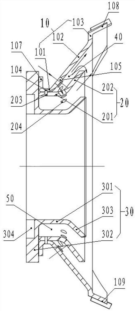
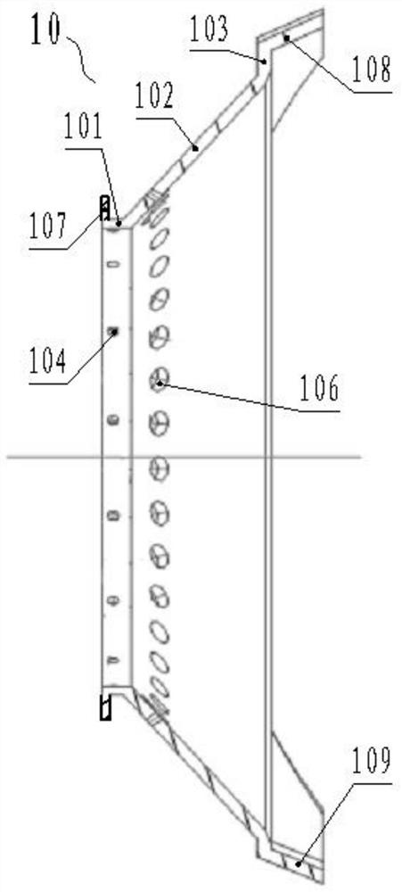
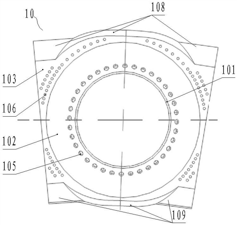
A cooling structure for the head of a flame tube of a combustion chamber of a medium-thrust aero-engine comprises a flow guide hole plate, a flow guide shield and a sleeve. The flow guide hole plate, the flow guide shield and the sleeve are coaxially arranged to form a first cooling gap and a second cooling gap, a plurality of first cooling holes are formed in the front section of the flow guide hole plate, a plurality of second cooling holes are formed in the conical section of the flow guide hole plate, and a plurality of third cooling holes are formed in the outlet section of the flow guide hole plate; a fourth cooling hole is formed in the front section of the flow guide shield; the first cooling hole and the fourth cooling hole are coaxially arranged and are communicated to the second cooling gap; and the second cooling hole is communicated with the first cooling gap. According to the invention, the generation of an invalid high-temperature trapped vortex area of fuel gas on the head of the combustion chamber close to the wall surface can be avoided, the cooling gas amount required by the head of the flame tube is reduced, the coverage area of head cooling gas flow is increased, the cooling efficiency is improved, the wall temperature of the head of the flame tube can be efficiently reduced, and the reliability of the head structure of the flame tube is improved.

Description

technical field [0001] The invention relates to the technical field of aero-engine combustor structures, in particular to a cooling structure for the head of a combustion chamber of an aero-engine combustor. Background technique [0002] The head of the flame tube of the engine combustion chamber is in a high-temperature environment for a long time, and it is prone to failures such as high-temperature ablation, deformation, cracks, and loss of blocks. Therefore, the cooling effect of the flame tube head directly affects the reliability of the structure of the combustion chamber head. [0003] The cooling of the flame tube is the basic requirement to ensure its normal operation. The flame tube of the combustion chamber at home and abroad has developed from the original pure gas film cooling to the composite cooling form of impact, divergence, gas film, laminate and other cooling. The cooling structure is also From the initial single-layer wall to double-wall, floating wall an...

Claims


Application Information

Patent Timeline
Patent Type & Authority Applications(China)
IPC IPC(8): F23R3/28
CPCF23R3/283
Inventor 赵婷杰卢铭涛何园源于小兵
Owner 中国航发贵阳发动机设计研究所
Why Eureka
Try Eureka