Fresh air ventilator, control method thereof and computer readable storage medium

A control method and technology for fresh air fans, applied in the field of control of fresh air fans, fresh air fans and computer-readable storage media, can solve the problems of high system energy consumption and high energy consumption, and achieve the effect of saving energy consumption and increasing heating capacity

Active Publication Date: 2022-03-01
GD MIDEA AIR-CONDITIONING EQUIP CO LTD
View PDF24 Cites 0 Cited by
  • Summary
  • Abstract
  • Description
  • Claims
  • Application Information

AI Technical Summary

Problems solved by technology

[0004] At present, when the heat of the heat pipe condenser is insufficient, the temperature and humidity of the fresh air can usually be adjusted to meet the comfort needs through heat pump or electric heating compensation, but this will cause high energy consumption of the system
It can be seen that there is a problem of high energy consumption in the process of fresh air dehumidification and reheating of fresh air fans

Method used


Image

  • Fresh air ventilator, control method thereof and computer readable storage medium
  • Fresh air ventilator, control method thereof and computer readable storage medium
  • Fresh air ventilator, control method thereof and computer readable storage medium

Examples


example 1

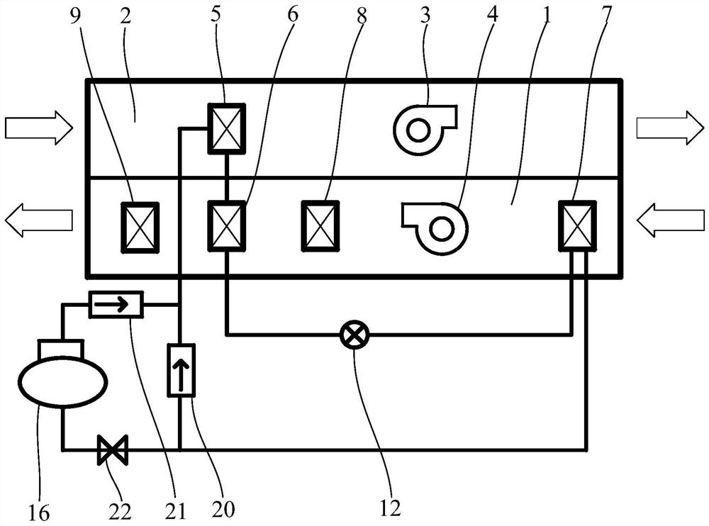
[0123] Example 1: The user sets the cooling mode, turns on the system operating components, when the fresh air temperature is 33°C = T1, and the exhaust air temperature is 23°C < T3, it is judged that energy-saving dehumidification and reheating are needed, the solenoid valve and the compressor are turned off, and the first section is turned on The exhaust air is heated to 26°C through the second heat exchanger, the fresh air is cooled to 27°C through the third heat exchanger, and then further cooled to 12°C through the dehumidification module, and then heated to 17°C by the second heat exchanger and sent into the indoor;

example 2

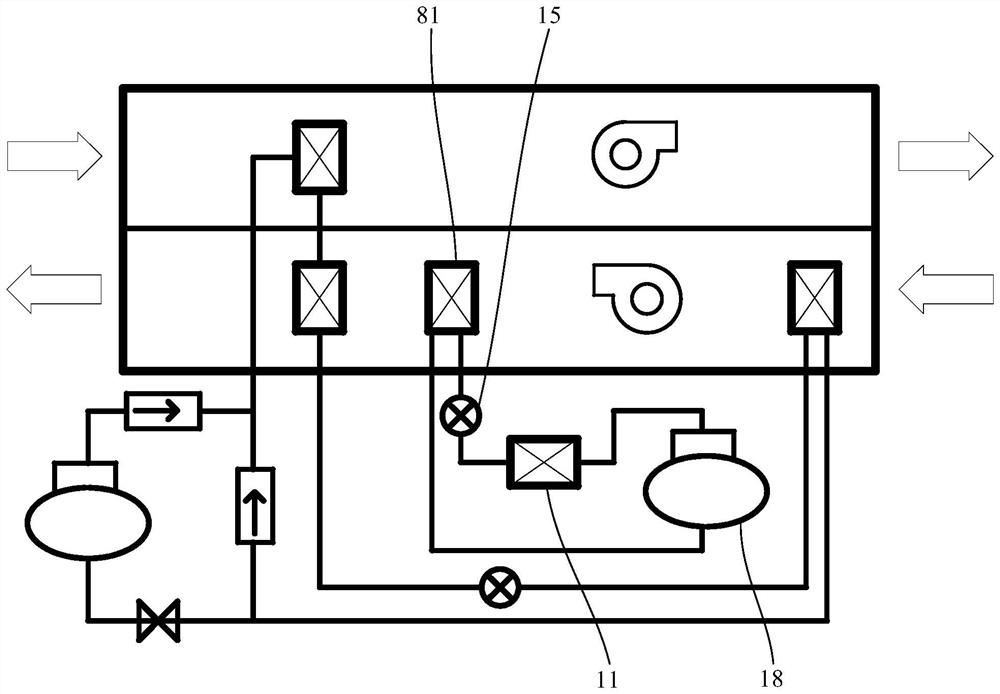
[0124] Example 2: The user sets the cooling mode and turns on the system operating components. When the fresh air temperature is 18°C

Embodiment

[0125] Example: the threshold T1 is 30-35°C, the threshold T1 is 20-25°C, the user sets 25°C, and the threshold T3 is 25°C±1°C.

[0126] Further, based on any of the above-mentioned embodiments, another embodiment of the control method of the fresh air fan of the present application is proposed. In this embodiment, the heat exchange module further includes a solenoid valve, a compressor, and a first one-way valve arranged between the refrigerant outlet of the third heat exchanger and the refrigerant inlet of the first heat exchanger , the compressor is connected in parallel with the first one-way valve, and the solenoid valve is connected in series with the compressor.

[0127] In an implementation manner of this embodiment, the control method of the new fan further includes: when starting the cooling operation, controlling the compressor to be turned off and the solenoid valve to be opened; after starting the cooling operation for a preset time, Execute the step of obtaining...


PUM


Abstract

The invention discloses a control method of a fresh air ventilator, the fresh air ventilator comprises a fresh air duct, an exhaust air duct, a heat exchange module and a dehumidification module, the heat exchange module comprises a first loop, the first loop comprises a first heat exchanger, a second heat exchanger, a first throttling device and a third heat exchanger which are connected in sequence, and the first heat exchanger is arranged in the exhaust air duct; the third heat exchanger, the dehumidification module and the second heat exchanger are sequentially arranged in the fresh air channel along the fresh air flow path, the dehumidification module is independent of the first loop, and the method comprises the steps that the fresh air temperature and/or the exhaust air temperature are/is obtained; a first control parameter of the heat exchange module and a second control parameter of the dehumidification module are determined according to the fresh air temperature and/or the exhaust air temperature; the heat exchange module is controlled to operate according to the first control parameter, and the dehumidification module is controlled to operate according to the second control parameter. The invention further discloses the fresh air ventilator and a readable storage medium. The fresh air temperature and humidity meet the comfort requirement, and meanwhile energy consumption is reduced.

Description

technical field [0001] The present invention relates to the technical field of fresh air blowers, in particular to a control method for fresh air blowers, a fresh air blower and a computer-readable storage medium. Background technique [0002] In recent years, with the improvement of people's quality of life, the quality of indoor air has been paid more and more attention. The fresh air unit is an important part of the room air conditioning system. On the one hand, it can send filtered fresh outdoor air into the room to replace the dirty air; on the other hand, it can perform heat and humidity treatment on the fresh air and bear part of the heat and humidity load of the room. [0003] The existing fresh air fan arranges the heat pipe heat exchanger before and after the cold source. The fresh air first passes through the heat pipe evaporator to absorb heat and cool down, then passes through the cold source for further dehumidification and cooling, and then is heated and heate...

Claims


Application Information

Patent Timeline
Patent Type & Authority Applications(China)
IPC IPC(8): F24F7/08F24F3/153F24F13/30F24F11/65F24F11/72F24F11/46F24F110/10F24F110/20
CPCF24F7/08F24F3/153F24F13/30F24F11/65F24F11/72F24F11/46F24F2110/10F24F2110/20
Inventor 杜顺开黄剑云高卓贤刘步东徐振坤李金波
Owner GD MIDEA AIR-CONDITIONING EQUIP CO LTD
Why Eureka
Try Eureka