Workpiece surface roughness and flatness detection device

A technology of workpiece surface and detection device, which is applied in the direction of mechanical roughness/irregularity measurement, etc., can solve the problems of insufficient efficiency of detection accuracy processing, product repair, and reduced workpiece detection efficiency, so as to improve the degree of detection automation. , improve efficiency and stability, improve the effect of stability and efficiency

Inactive Publication Date: 2022-03-01
潘碎斌
View PDF0 Cites 4 Cited by
  • Summary
  • Abstract
  • Description
  • Claims
  • Application Information

AI Technical Summary

Problems solved by technology

[0002] After the processing of many existing workpieces, the surface roughness and flatness of the workpiece need to be tested. If the surface roughness of the processed workpiece does not meet the standards, there will be problems with the accuracy in subsequent processing, thus It may cause the entire product to be repaired, affecting the efficiency of subsequent product production.
[0003] However, the existing workpiece surface roughness testing equipment can only detect the roughness of the workpiece to be tested. When testing its flatness, it needs to be transported to other machines for testing, which reduces the efficiency of testing the workpiece. Some testing equipment also has insufficient detection accuracy and processing efficiency for unqualified workpieces, which will subsequently affect the production efficiency of workpieces

Method used


Image

  • Workpiece surface roughness and flatness detection device
  • Workpiece surface roughness and flatness detection device
  • Workpiece surface roughness and flatness detection device

Examples


Embodiment Construction

[0028] The following will clearly and completely describe the technical solutions in the embodiments of the present invention with reference to the accompanying drawings in the embodiments of the present invention. Obviously, the described embodiments are only some, not all, embodiments of the present invention. Based on the embodiments of the present invention, all other embodiments obtained by persons of ordinary skill in the art without making creative efforts belong to the protection scope of the present invention.

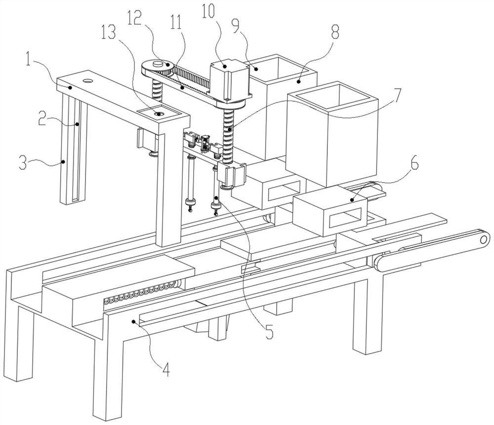
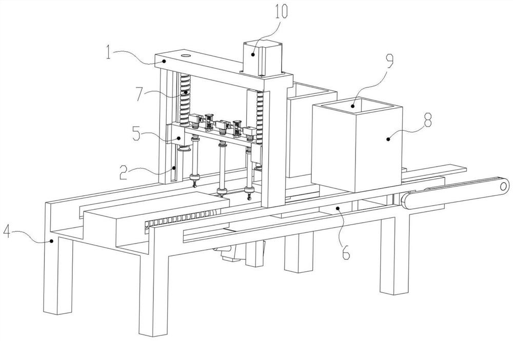
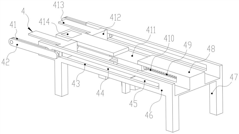
[0029] see Figure 1-9 , an embodiment provided by the present invention: a workpiece surface roughness and flatness detection device, including a support frame 1, a guide chute 2, a limit clamp 3, a material guide mechanism 4, a detection mechanism 5, and a connecting workpiece 6 , threaded rod 7, material storage box 8, guide groove 9, servo motor 10, connecting belt 11, connecting pulley 12 and shaft groove 13,

[0030]The upper end surface of the material...


PUM


Abstract

The invention discloses a workpiece surface roughness and flatness detection device which comprises a supporting frame, a guiding sliding groove, a limiting clamping plate, a material guiding mechanism, a detection mechanism, a connecting workpiece, a threaded rod, a material storage box, a guiding groove, a servo motor, a connecting belt, a connecting belt wheel and a rotating shaft groove. A supporting frame used for supporting is fixedly installed at the position, close to the center, of the upper end face of the material guiding mechanism, and limiting clamping plates are symmetrically and fixedly installed on the lower end face of the supporting frame. By arranging the workpiece template, a connecting workpiece can be compared with a standard part during detection, so that the efficiency and the stability of subsequent detection of the connecting workpiece are improved to the greatest extent, meanwhile, two groups of supporting sliding grooves are formed, two groups of connecting workpieces can be detected at the same time, the speed of detecting the connecting workpiece is effectively improved, and the detection accuracy is improved. And the detection efficiency is improved.

Description

technical field [0001] The invention relates to the technical field of detection equipment, in particular to a detection device for workpiece surface roughness and flatness. Background technique [0002] After the processing of many existing workpieces, the surface roughness and flatness of the workpiece need to be tested. If the surface roughness of the processed workpiece does not meet the standards, there will be problems with the accuracy in subsequent processing, thus It may cause the entire product to be repaired, affecting the efficiency of subsequent product production. [0003] However, the existing workpiece surface roughness testing equipment can only detect the roughness of the workpiece to be tested. When testing its flatness, it needs to be transported to other machines for testing, which reduces the efficiency of testing the workpiece. Some testing equipment also has insufficient detection accuracy and processing efficiency for unqualified workpieces, which w...

Claims


Application Information

Patent Timeline
Patent Type & Authority Applications(China)
IPC IPC(8): G01B5/28
CPCG01B5/28
Inventor 潘碎斌
Owner 潘碎斌
Why Eureka
Try Eureka