Method for automatically determining pose of large-aperture element

An automatic determination and large-aperture technology, applied in the field of engineering optics, can solve problems such as uncertain component poses and limited positioning accuracy, and achieve the effect of avoiding manual intervention and improving detection accuracy

Pending Publication Date: 2022-03-01
HARBIN INST OF TECH
View PDF0 Cites 1 Cited by
  • Summary
  • Abstract
  • Description
  • Claims
  • Application Information

AI Technical Summary

Problems solved by technology

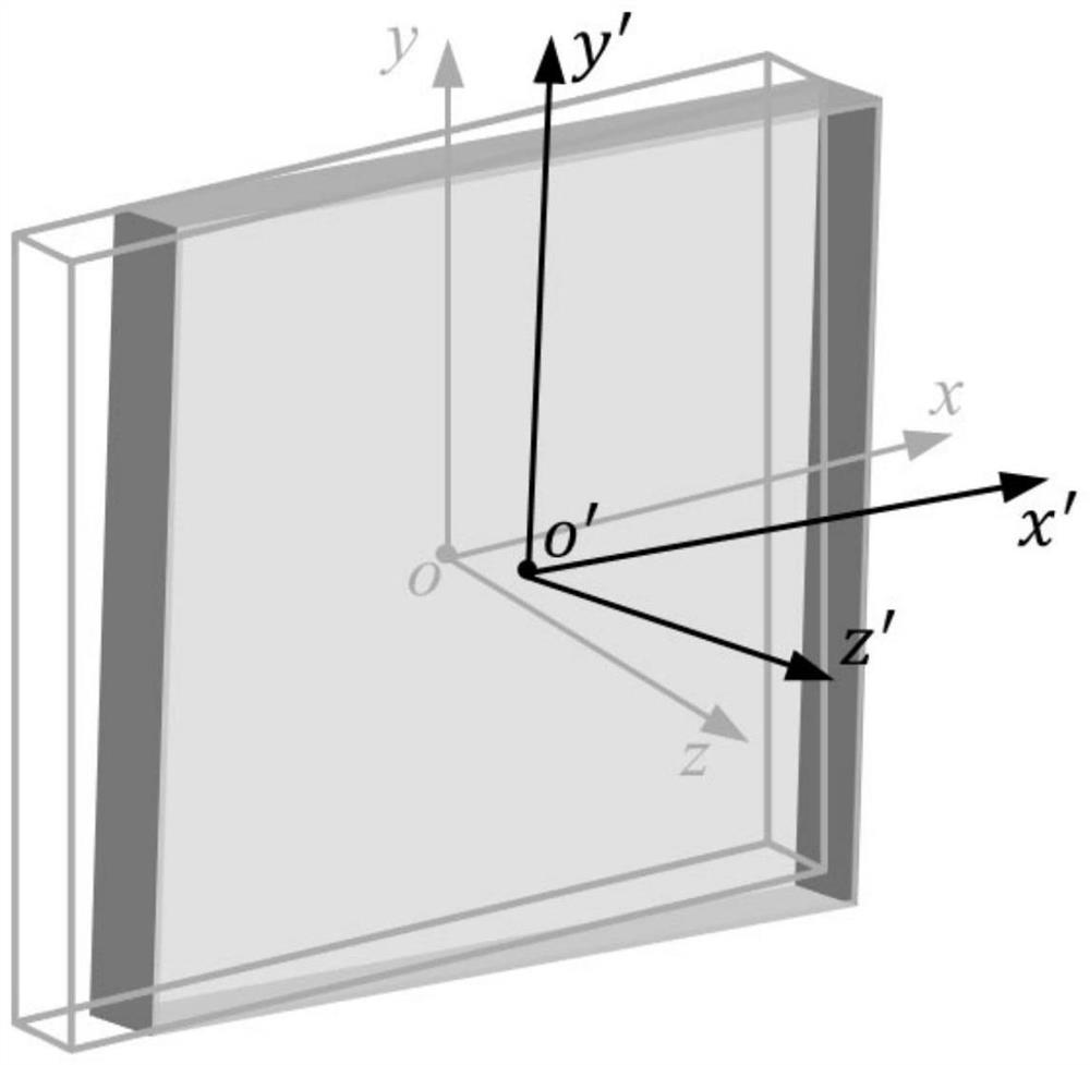
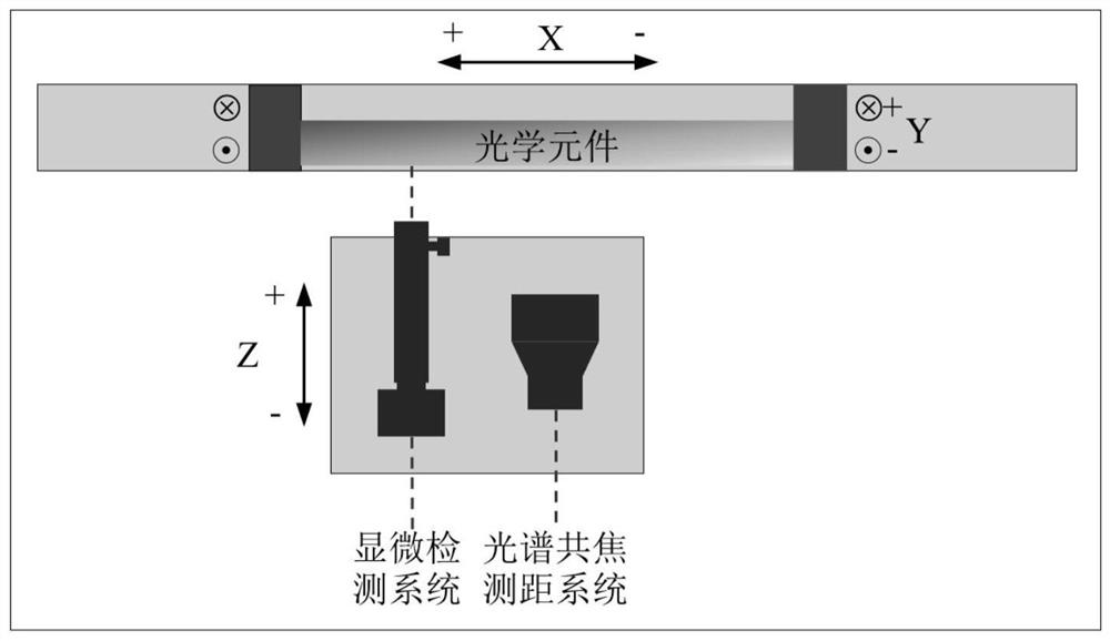
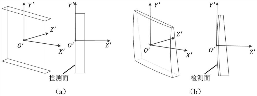
[0005] In view of the above problems, the present invention proposes a method for automatically determining the pose of a large-diameter component to solve the problem of uncertain pose of the component due to the limited positioning accuracy of the component fixture on the machine tool. The present invention is used to determine the installation position of the component on the machine tool calibration pose

Method used


Image

  • Method for automatically determining pose of large-aperture element
  • Method for automatically determining pose of large-aperture element
  • Method for automatically determining pose of large-aperture element

Examples


Embodiment Construction

[0059] In order to enable those skilled in the art to better understand the solutions of the present invention, exemplary implementations or embodiments of the present invention will be described below in conjunction with the accompanying drawings. Apparently, the described embodiments or examples are only part of the embodiments or embodiments of the present invention, not all of them. Based on the implementation modes or examples in the present invention, all other implementation modes or examples obtained by persons of ordinary skill in the art without creative efforts shall fall within the protection scope of the present invention.

[0060] An embodiment of the present invention provides a method for automatically determining the pose of a large-diameter component, the method including the following steps:

[0061] Step 1. Collect multiple images of the components in the current pose on the machine tool, and process the multiple images to obtain the translation error and d...


PUM


Abstract

The invention discloses an automatic pose determination method for a large-aperture element, relates to the technical field of engineering optics, and is used for solving the problem that the pose of the element is uncertain due to limited positioning precision of an element clamp on a machine tool. The method is technically characterized by comprising the steps that a plurality of images of an element of the current pose on a machine tool are collected and processed, translation errors and deflection errors of any point on the element relative to the calibration pose of the element under a machine tool coordinate system are obtained, the translation errors comprise X-axis translation errors, Y-axis translation errors and Z-axis translation errors, and the deflection errors comprise X-axis deflection errors and Y-axis deflection errors; and calculating according to the translation error and the deflection error to obtain the calibration attitude of the element. According to the method, the problem that the element pose is uncertain due to limited clamp positioning precision is solved, the calibration coordinates of the point on the element moving to any station on the machine tool are obtained, and accurate position reference is provided for subsequent positioning and repairing of the defect point.

Description

technical field [0001] The invention relates to the technical field of engineering optics, in particular to a method for automatically determining the pose of a large-caliber element. Background technique [0002] Large-aperture optical components in high-power solid-state laser devices are prone to surface damage under strong laser irradiation. If these damages cannot be repaired in time, they will accelerate and expand under subsequent laser irradiation, eventually leading to component failure. In order to improve the service life of components, CO is used in engineering 2 The laser repair method is used to repair the damaged components off-line. Studies have shown that this repair method can effectively improve the damage threshold of the material and inhibit the growth of surface defects without affecting the optical performance of the component. The repaired components can be loaded into the circuit for continuous use, which saves the maintenance cost of the device. ...

Claims


Application Information

Patent Timeline
Patent Type & Authority Applications(China)
IPC IPC(8): G01B11/00
CPCG01B11/002
Inventor 赵林杰陈明君尹朝阳程健袁晓东郑万国廖威王海军张传超
Owner HARBIN INST OF TECH
Why Eureka
Try Eureka