Visual carrier landing guiding method and system for unmanned rotorcraft

A guidance system and unmanned rotor technology, applied in the aerospace field, can solve the problems that affect the stability of UAV landing and the data link electromagnetic signal is susceptible to external interference, etc.

Pending Publication Date: 2022-03-01
CHINA HELICOPTER RES & DEV INST
View PDF12 Cites 0 Cited by
  • Summary
  • Abstract
  • Description
  • Claims
  • Application Information

AI Technical Summary

Problems solved by technology

[0003] In practical engineering applications, both of these two landing guidance methods have the problem of relying on the measurement and control data link, because the electromagnetic signal of the data link is susceptible to external interference, which will affect the landing stability of the UAV.

Method used


Image

  • Visual carrier landing guiding method and system for unmanned rotorcraft
  • Visual carrier landing guiding method and system for unmanned rotorcraft
  • Visual carrier landing guiding method and system for unmanned rotorcraft

Examples


Embodiment 1

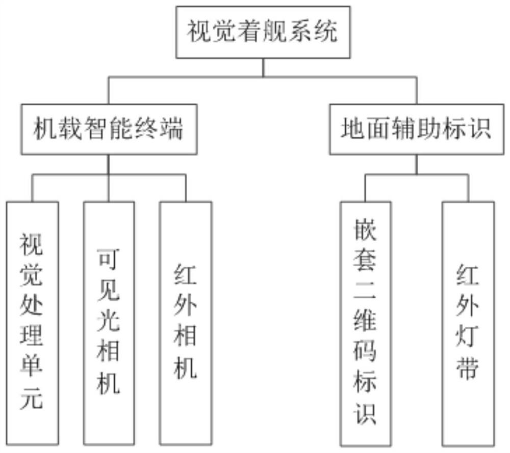
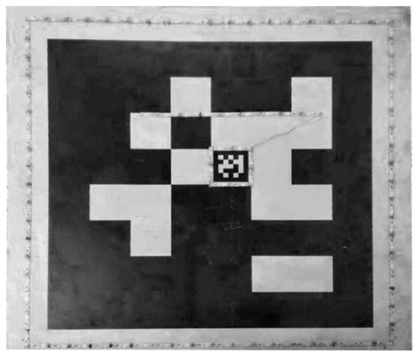
[0028] to combine figure 2 As shown, this embodiment provides a rotary-wing UAV visual landing guidance system, including an airborne intelligent terminal and ground auxiliary identification; the airborne intelligent terminal includes a visual processing unit, a visible light camera and an infrared camera. Ground auxiliary signs include nested two-dimensional code signs and infrared light strips around the two-dimensional code signs. Nested two-dimensional code signs include inner two-dimensional codes and outer two-dimensional codes. The inner two-dimensional code is nested in the outer layer. QR code.

[0029] The visible light camera or the infrared camera is used to obtain the image information of the ground auxiliary marking in real time and send it to the vision processing unit.

[0030] The visual processing unit compares the received image information with the target image library in the visual processing unit, obtains the speed required for the landing of the drone ...

Embodiment 2

[0037] This embodiment provides a visual landing guidance method for a rotary-wing unmanned aerial vehicle, using the above-mentioned landing guidance system, the guidance method includes:

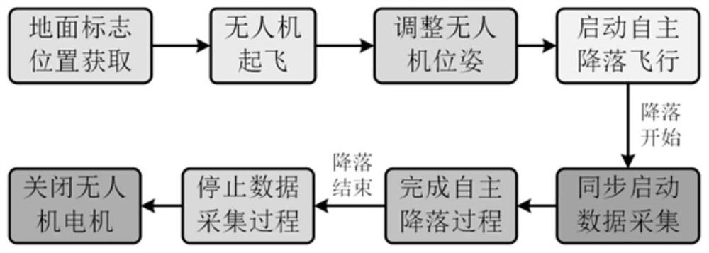
[0038] Step 1: Collect a large number of target images in the landing area through visible light cameras and infrared cameras, and establish a training library of target images in the landing area; the data contained in the target images in the landing area include image data of the ground environment and landing platform environment; the acquisition process covers different time, different lighting conditions and different background environments. The image acquisition process is as figure 1 shown.

[0039] Step 2: For each image collected in the target image training library, calibrate the speed corresponding to the rotor drone at the time of each image collection, as the label data; the speed includes υ x, υ y , υ z , ω z , are the linear velocity in the heading x, longitudinal y, ...


PUM


Abstract

The invention belongs to the technical field of aerospace, and particularly relates to a rotor unmanned aerial vehicle visual carrier landing guiding method and system. Comprising an airborne intelligent terminal and a ground auxiliary identifier. The airborne intelligent terminal comprises a visual processing unit, a visible light camera and an infrared camera, and the visible light camera or the infrared camera is used for obtaining ground auxiliary identification image information in real time and sending the ground auxiliary identification image information to the visual processing unit; the visual processing unit compares the received image information with a target image library in the visual processing unit, obtains the speed quantity required by the landing of the unmanned aerial vehicle corresponding to the current image acquisition moment, and feeds back the speed quantity to the flight control system; the flight control system judges whether the current speed of the unmanned aerial vehicle meets the speed quantity required by landing of the unmanned aerial vehicle; according to the invention, based on visual servo control of the image, autonomous landing of the unmanned aerial vehicle under supervision control is realized.

Description

technical field [0001] The invention belongs to the technical field of aerospace, and in particular relates to a visual landing guidance method and system for a rotor UAV. Background technique [0002] At present, domestic and foreign technologies that are maturely applied to the automatic landing guidance of rotor UAVs mainly include radar guidance and differential satellite guidance. Track and calculate the relative position information between the UAV and the ship, upload it to the UAV through the measurement and control data link, and guide the UAV to complete the ship control; the differential satellite guidance method obtains differential observation by arranging a differential satellite station on the carrier platform The amount of information is uploaded to the UAV through the measurement and control data link, and the real-time dynamic (RTK, Real-time Kinematic) calculation is performed with the airborne differential satellite information to form high-precision rela...

Claims


Application Information

Patent Timeline
Patent Type & Authority Applications(China)
IPC IPC(8): G05D1/10
CPCG05D1/101
Inventor 宋平李瑜强李怡伟张大高田学稳宋海薇宋乐肖光华张茂
Owner CHINA HELICOPTER RES & DEV INST
Why Eureka
Try Eureka