Miniaturized low-frequency oscillator unit and antenna array

A low-frequency vibrator and antenna array technology, which is applied to antenna arrays, antenna arrays, antennas and other directions that are energized separately, can solve the problems of large aperture, unfavorable antenna miniaturization, and large impact, and achieve the effect of improving isolation.

Active Publication Date: 2022-03-01
GUANGDONG BROADRADIO COMM TECH
View PDF9 Cites 2 Cited by
  • Summary
  • Abstract
  • Description
  • Claims
  • Application Information

AI Technical Summary

Problems solved by technology

[0003] In recent years, low-frequency vibrator units use more cross-shaped and X-shaped vibrator units. This type of vibrator unit can be flexibly arrayed and has less shielding from adjacent high-frequency vibrator units. However, this type of low-frequency vibrator unit is generally larger in diameter. , when there are two low-frequency systems, the influence between the two low-frequency systems is greater, which is not conducive to the miniaturization of the antenna

Method used


Image

  • Miniaturized low-frequency oscillator unit and antenna array
  • Miniaturized low-frequency oscillator unit and antenna array
  • Miniaturized low-frequency oscillator unit and antenna array

Examples


Embodiment 1

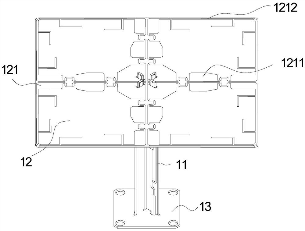
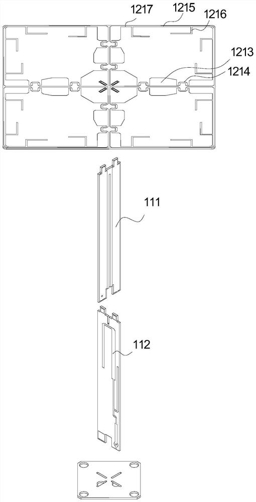
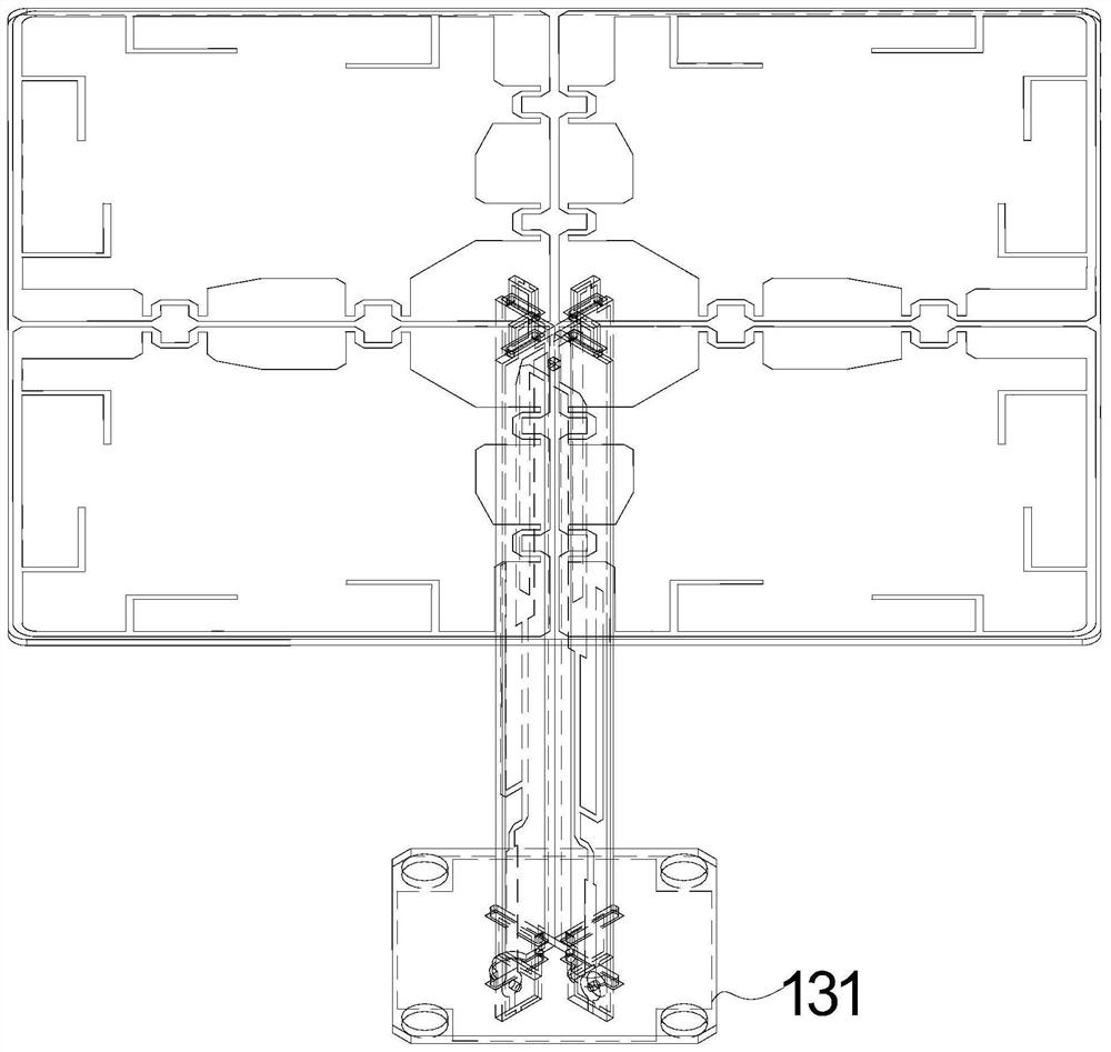
[0044] see Figure 1-Figure 3 , the present embodiment provides a miniaturized low-frequency oscillator unit, including two orthogonally inserted oscillator pieces 11 , and a base plate 13 and a radiation piece 12 respectively connected to both ends of the oscillator pieces 11 . The radiation sheet 12 is composed of four dipole arms 121 , and the four dipole arms 121 are arranged in pairs in an orthogonal and symmetrical manner to form two pairs of dipoles whose polarization directions are orthogonal to each other.

[0045]The vibrator arm 121 is composed of two sections of the first radiating arm 1211 and two sections of the second radiating arm 1212 forming a box; the first radiating arm 1211 is coupled with the first radiating arm 1211 of the adjacent dipole, which can effectively reduce the low frequency The aperture of the vibrator unit, and the first radiating arm 1211 is composed of thick copper foil 1213 and curved thin copper foil 1214 connected at intervals. The ben...

Embodiment 2

[0057] Figure 5 Another antenna array is shown, including a reflector 2 , and a low-frequency base station antenna array, a high-frequency base station antenna array 32 and a high-frequency smart antenna array 33 all installed on the reflector 2 . The high-frequency base station antenna array 32 is arranged on both sides of the reflector 2, the high-frequency smart antenna array 33 is arranged in the middle of the reflector 2, and the low-frequency base station antenna array is embedded with the high-frequency base station antenna array 32 and the high-frequency smart antenna array 33. set. They form a TDD+FDD hybrid antenna array, so that the antennas of different systems working in different frequency bands share the reflector and radome, and realize the multi-system integrated design, which is conducive to the miniaturization of the antenna and saves installation space.

[0058] Wherein, the low-frequency base station antenna array is formed by two rows of low-frequency o...


PUM


Abstract

The invention discloses a miniaturized low-frequency oscillator unit and an antenna array, and the low-frequency oscillator unit comprises a base plate which is printed with a first circuit; second circuits are printed on the oscillator sheets, one ends of the oscillator sheets are fixed on the base plate, and the second circuits are electrically connected with the first circuits; the radiation sheet is fixed at the other end of the oscillator sheet, the radiation sheet comprises four oscillator arms which are mutually symmetrical, each oscillator arm comprises two sections of first radiation arms and two sections of second radiation arms, the first radiation arms are formed by connecting thick copper foils and thin copper foils at intervals, the second radiation arms are made of thin copper foils, and the thick copper foils and the thin copper foils are connected at intervals. The second circuit is electrically connected with the oscillator arm; and two orthogonal dipoles are formed by the vibrator arms which are not adjacent to each other. The oscillator arms are mutually coupled through the first radiation arms, so that the miniaturization of the oscillator can be realized, and the antenna can be widely applied to the technical field of antennas.

Description

technical field [0001] The invention relates to the technical field of antennas, in particular to a miniaturized low-frequency oscillator unit and an antenna array. Background technique [0002] With the rapid development of wireless communication, base station antennas are developing towards multi-frequency, multi-port and multi-standard. From the two-port antenna of the base station antenna in the 2G era to the antenna with more than 6 ports using MIMO function in the 4G era, to the large-scale antenna array in the 5G era. With the increase of frequency bands and the shortage of site resources, operators need to deploy more base station systems in as few sites as possible, which puts forward higher requirements for antennas, and integrated full-band antennas have become the mainstream demand. The high and low frequency systems of the integrated multi-band antenna have a great influence on each other, and the size is mainly determined by the size of the low frequency syste...

Claims


Application Information

Patent Timeline
Patent Type & Authority Applications(China)
IPC IPC(8): H01Q1/52H01Q21/06H01Q21/08
CPCH01Q21/061H01Q1/523H01Q21/08
Inventor 张劭吴泽海罗本波彭传威
Owner GUANGDONG BROADRADIO COMM TECH
Why Eureka
Try Eureka