Motor stator iron core, manufacturing method of motor stator iron core and laminating tool

A technology for motor stator and lamination tooling, which is applied in the manufacture of stator/rotor bodies, electromechanical devices, and motor generators, etc. The effect of consistency, simple fixation, and low manufacturing cost

Pending Publication Date: 2022-03-01
HENAN BENMA
View PDF13 Cites 2 Cited by
  • Summary
  • Abstract
  • Description
  • Claims
  • Application Information

AI Technical Summary

Problems solved by technology

[0004] The purpose of the present invention is to provide a motor stator core to solve the problems of complex installation process, high cost and high welding process requirements of the motor stator core in the prior art;
[0005] The object of the present invention is also to provide a manufacturing method of a motor stator core to solve the problem of complex installation process or high cost when the motor stator core is fastened by the buckle method in the prior art, and the welding method is used for fastening The requirements for welding process are high, and it is easy to cause the problem of thermal deformation of silicon steel sheet during welding;
[0006] The object of the present invention is also to provide a lamination tooling for motor stator cores to solve the problem of complex structure of the lamination tooling for motor stator cores in the prior art

Method used


Image

  • Motor stator iron core, manufacturing method of motor stator iron core and laminating tool
  • Motor stator iron core, manufacturing method of motor stator iron core and laminating tool
  • Motor stator iron core, manufacturing method of motor stator iron core and laminating tool

Examples


specific Embodiment 1

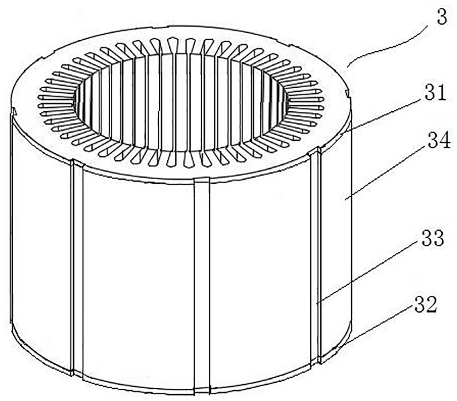
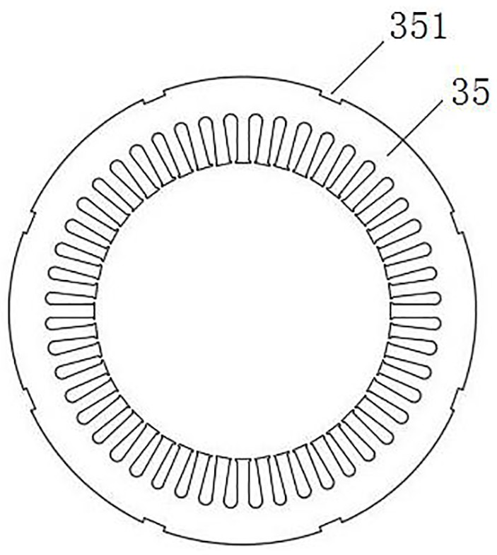
[0055] Such as figure 1 with figure 2 As shown, the motor stator core 3 includes a first end plate 31, a second end plate 32 and an iron core body 34. The first end plate 31 and the second end plate 32 are arranged at both ends of the iron core body 34 in the axial direction. The silicon steel sheets 35 of the core body 34 are stacked between the two end plates, so that the silicon steel sheets 35 are axially positioned by the two end plates. The above-mentioned iron core main body 34 constitutes the middle part, and the first end plate 31 and the second end plate 32 constitute two end parts, wherein, the number of silicon steel sheets 35 of the iron core main body 34 can be determined according to the axial length of the motor stator iron core 3 set up.

[0056] In this embodiment, both the first end plate 31 and the second end plate 32 are composed of a plurality of silicon steel sheets 35, and the structures of the two end plates are the same, only the positions are diff...

specific Embodiment 2

[0062] Compared with the specific embodiment 1 of the motor stator core of the present invention, the difference is that the motor stator core in this embodiment is not provided with an end plate, and all the silicon steel sheets are fixed together by the colloidal action of the through groove to form an iron core main body.

specific Embodiment 3

[0064] Compared with the specific embodiment 1 of the motor stator core of the present invention, the difference is that: the first end plate and the second end plate of the motor stator core in this embodiment are all carbon steel end plates, and the first end plate, the second end plate The two end plates mainly play the role of pressing and positioning the main body of the iron core. In other embodiments, one of the first end plate and the second end plate may also be composed of multiple silicon steel sheets laminated and fixed, and the other may be a carbon steel end plate.

[0065] Specific embodiment 1 of the laminated tooling of the motor stator core of the present invention:

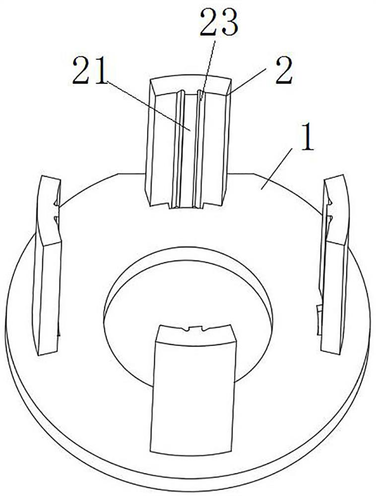
[0066] Such as image 3 As shown, the lamination tooling of the stator core of the motor includes a support seat 1 and four positioning plates 2. The shape and size of the four positioning plates 2 are exactly the same, and the four positioning plates 2 are evenly spaced along the circumferenti...


PUM


Abstract

The invention relates to a motor stator iron core, a manufacturing method of the motor stator iron core and a laminating tool. The motor stator core comprises silicon steel sheets, the silicon steel sheets are stacked, and the edge of the radial outer side of each silicon steel sheet is provided with a groove; the grooves on the silicon steel sheets form through grooves on the radial outer side of the motor stator core, and the through grooves extend along the axial direction of the motor stator core. Through groove colloids are arranged in all the through grooves, or through groove colloids are arranged in part of the through grooves, and all the silicon steel sheets are fixed together under the bonding effect of the through groove colloids. The silicon steel sheets of the motor stator iron core are bonded and fixed through the through groove colloid, and compared with an outer buckle sheet method, the motor stator iron core has the advantage of being simple in installation process; compared with an inner buckle sheet method, elastic buckles do not need to be stamped on the silicon steel sheets, a special stamping die is not needed correspondingly, the method has the advantages of being low in manufacturing cost, convenient and rapid, and compared with a welding method, welding is not needed, and high-temperature deformation of the silicon steel sheets cannot be caused.

Description

technical field [0001] The invention relates to a motor stator core, a manufacturing method of the motor stator core and a laminated tooling. Background technique [0002] The stator core lamination of existing motors is mostly tire-expanding lamination. This kind of stator lamination tooling has a complex structure, long processing cycle, and requires the production of exclusive slot molds for positioning during lamination. Such as the motor stator iron core lamination fast expansion device disclosed in the patent whose authorized notification number is CN204928505U. [0003] In addition, the stator needs to be fastened after lamination. At present, there are three methods of fastening the stator core laminations: the outer buckle method, the inner buckle method and the welding method. The outer buckle method is to add a dovetail buckle in the outer or inner circle of the lamination. This method needs to make a dovetail buckle for each kind of lamination, and the installat...

Claims


Application Information

Patent Timeline
Patent Type & Authority Applications(China)
IPC IPC(8): H02K1/12H02K1/18H02K15/02
CPCH02K1/12H02K1/18H02K15/026
Inventor 胡学军翟秀果李毅拓李斌
Owner HENAN BENMA
Why Eureka
Try Eureka