
Dimming method using MCU (Microprogrammed Control Unit) coding

A dimming and encoding technology, applied in energy-saving control technology, electrical components, etc., can solve the problems of EMI index is not easy to meet the standard, control dimming is not smooth enough, analog dimming applications are not many, etc., to achieve easy control, dimming voltage Stable and reliable effect

Active Publication Date: 2022-03-01
SHANGHAI SINOMICON ELECTRONICS
View PDF6 Cites 0 Cited by
  • Summary
  • Abstract
  • Description
  • Claims
  • Application Information

AI Technical Summary

Problems solved by technology

[0002] There are generally two existing LED lighting dimming methods, one is analog dimming, and the other is pulse width modulation, that is, PWM dimming. Analog dimming changes the current I flowing through the LED (I=V R / R) Change the brightness of the LED, and the change circuit I usually uses the change of the analog voltage V R Realization, the advantage of this method is that the current is stable, the current will not change sharply, and the EMI test is easy to meet the standard, but in practical applications, due to the troublesome control and poor anti-interference ability, there are not many analog dimming applications, so most of them use PWM dimming, PWM dimming circuit output is pulse current, the average value of pulse current is LED current I, changing the duty ratio of pulse signal can change the value of I, its advantage is strong anti-interference ability, but control The dimming is not smooth enough, and the EMI index is not easy to meet the standard

Method used


Image

  • Dimming method using MCU (Microprogrammed Control Unit) coding
  • Dimming method using MCU (Microprogrammed Control Unit) coding
  • Dimming method using MCU (Microprogrammed Control Unit) coding

Examples


Embodiment Construction

[0024] The following will clearly and completely describe the technical solutions in the embodiments of the present invention with reference to the accompanying drawings in the embodiments of the present invention. Obviously, the described embodiments are only some, not all, embodiments of the present invention.

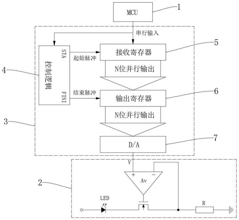
[0025] refer to Figure 1-3 , a dimming method coded with an MCU, comprising the following steps:

[0026] A. The signal is serially input; the single-chip microcomputer 1 converts the dimming command into a serial data flow signal output;

[0027] B, signal decoding control; The control logic circuit 4 decodes the serial data stream signal into a start pulse signal and an end pulse signal, and is output by the STA end and the FINI end of the control logic circuit 4 respectively;

[0028] C, initial control output; the receiving register 5 receives the serial data flow signal output by the single-chip microcomputer 1, and the control logic circuit 4 outputs the init...


PUM


Abstract

The invention discloses a dimming method using MCU (Microprogrammed Control Unit) coding. The dimming method comprises the following steps of: serially inputting a signal; signal decoding control; starting control output; ending the control output; performing digital-to-analog conversion output; analog signal dimming; a dimming circuit used by the dimming method using MCU coding comprises a single-chip microcomputer used for controlling and sending serial data stream signals and an analog dimming circuit used for dimming through analog signals, and a signal conversion unit is connected between the single-chip microcomputer and the analog dimming circuit. Through a signal conversion mode, a serial data stream signal for dimming control is converted into an analog signal to be output to the analog dimming circuit for dimming, the dimming voltage is stable, the dimming circuit is suitable for dimming of various power devices, the EMI index can be easily controlled within a reasonable range, and the reliability is higher.

Description

technical field [0001] The invention relates to the field of LED dimming control, in particular to a dimming method coded by an MCU. Background technique [0002] There are generally two existing LED lighting dimming methods, one is analog dimming, and the other is pulse width modulation, that is, PWM dimming. Analog dimming changes the current I flowing through the LED (I=V R / R) Change the brightness of the LED, and the change circuit I usually uses the change of the analog voltage V R Realization, the advantage of this method is that the current is stable, the current will not change sharply, and the EMI test is easy to meet the standard, but in practical applications, due to the troublesome control and poor anti-interference ability, there are not many analog dimming applications, so most of them use PWM dimming, PWM dimming circuit output is pulse current, the average value of pulse current is LED current I, changing the duty ratio of pulse signal can change the value ...

Claims


Application Information

Patent Timeline
Patent Type & Authority Applications(China)
IPC IPC(8): H05B45/10
CPCH05B45/10Y02B20/40
Inventor 王小明赵文博
Owner SHANGHAI SINOMICON ELECTRONICS
Learn More