
Intelligent hydraulic damping device for new energy automobile marketing

A new energy vehicle, hydraulic shock absorption technology, applied in the field of auto parts, can solve the problems of inability to adjust the damping force, inability to adjust the stretching length of the spring, and different sizes

Inactive Publication Date: 2022-03-04
江西环境工程职业学院
View PDF0 Cites 0 Cited by
  • Summary
  • Abstract
  • Description
  • Claims
  • Application Information

AI Technical Summary

Problems solved by technology

[0004] The problem to be solved by the present invention is to provide an intelligent hydraulic shock absorber for new energy vehicle marketing, which solves the problem that the existing shock absorber generates vibration through the impact of the elastic element, and uses the elastic deformation of the spring to improve the ride comfort of the car. The fixed distance between the two ends of the spring remains unchanged, and the stretching length of the spring cannot be adjusted according to the actual road conditions; at the same time, the piston in the shock absorber moves up and down, and the oil in the shock absorber chamber repeatedly passes through different chambers. The pores of the hole flow into another cavity. At this time, the friction between the hole wall and the oil and the internal friction between the oil molecules form a damping force on the vibration. Since the size of the hole remains unchanged, the resulting damping force is different and cannot be controlled. The technical problem of regulating the damping force generated

Method used


Image

  • Intelligent hydraulic damping device for new energy automobile marketing
  • Intelligent hydraulic damping device for new energy automobile marketing
  • Intelligent hydraulic damping device for new energy automobile marketing

Examples


Embodiment Construction

[0025] The following will clearly and completely describe the technical solutions in the embodiments of the present invention with reference to the accompanying drawings in the embodiments of the present invention. Obviously, the described embodiments are only some, not all, embodiments of the present invention. Based on the embodiments of the present invention, all other embodiments obtained by persons of ordinary skill in the art without creative efforts fall within the protection scope of the present invention.

[0026] Specific examples are given below.

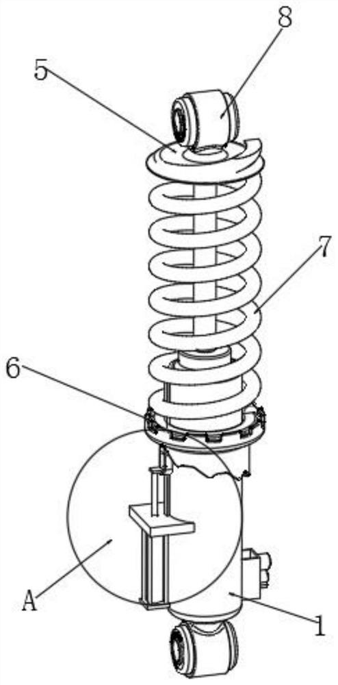
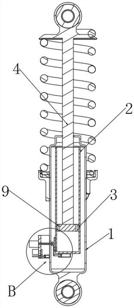
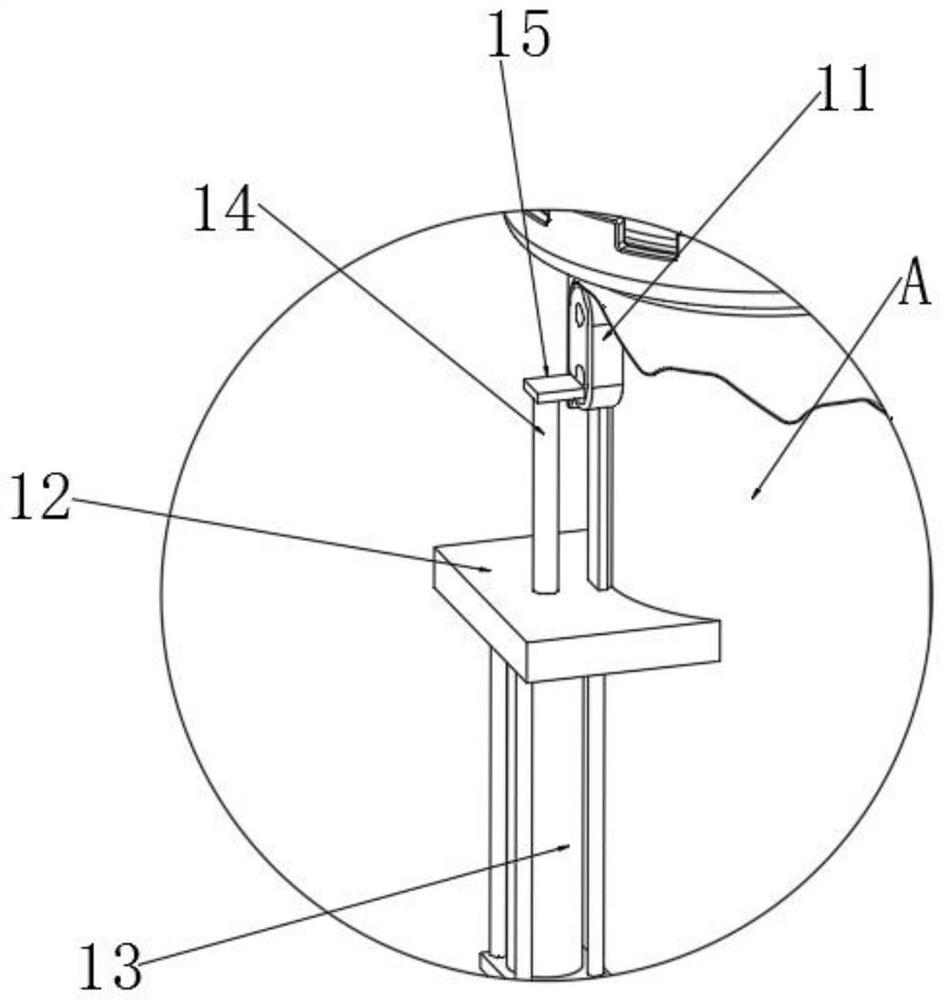
[0027] see Figure 1~Figure 4 , an intelligent hydraulic damping device for marketing new energy vehicles, comprising an outer cylinder 1 and an inner cylinder 2, the inner cylinder 2 is installed in the conduction of the outer cylinder 1, and the top of the inner cylinder 2 is installed with a first piston rod 4, One end of the first piston rod 4 is located inside the inner cylinder 2, and a piston 3 is installed, and t...


PUM


Abstract

The intelligent hydraulic damping device for new energy automobile marketing comprises an outer cylinder and an inner cylinder, the inner cylinder is installed in the outer cylinder in a communicating mode, a first piston rod is installed at the top of the inner cylinder in a penetrating mode, a piston is installed at the position, located in the inner cylinder, of one end of the first piston rod, and a circulation valve is arranged on the piston; a limiting check block is installed at the other end of the first piston rod, a movable check block is installed on the outer side of the outer cylinder in a sliding mode, a spring is arranged between the limiting check block and the movable check block and located on the outer side of the first piston rod in a sleeving mode, and connecting lug bases are arranged on the limiting check block and the sliding base. Different buffer holes are matched with the compensation holes, at the moment, during application, the different buffer holes are communicated with the compensation holes, damping force formed by friction of oil between the buffer holes and internal friction between oil molecules on vibration is manually regulated and controlled, the damping effect of the device is adjusted, and practical application is facilitated.

Description

technical field [0001] The invention relates to the technical field of auto parts, in particular to an intelligent hydraulic damping device used for marketing new energy vehicles. Background technique [0002] The shock absorber is used to suppress the shock when the spring rebounds after absorbing the shock and the impact from the road surface. It is widely used in automobiles to accelerate the attenuation of frame and body vibrations and improve the ride comfort of automobiles. [0003] The existing shock absorbing device vibrates through the impact of the elastic element, and uses the elastic deformation of the spring to improve the ride comfort of the car, but the fixed distance between the two ends of the spring remains unchanged, and the stretching length of the spring cannot be adjusted according to the actual road conditions; At the same time, the piston in the shock absorber moves up and down, and the oil in the shock absorber cavity repeatedly flows from one cavit...

Claims


Application Information

Patent Timeline
Patent Type & Authority Applications(China)
IPC IPC(8): F16F13/00F16F1/12F16F9/34F16F9/46
CPCF16F13/007F16F1/121F16F9/34F16F9/461F16F9/462F16F9/467F16F2230/0005
Inventor 张小联李活刘扬柏
Owner 江西环境工程职业学院
Learn More