
Infrared detection chip and infrared detector

An infrared detection and chip technology, applied in the field of infrared detection, can solve the problems of limited promotion, difficult removal of mechanical noise, control of residual stress and surface roughness to be improved, and achieve simple structure and preparation process, high sensitivity and low cost Effect

Pending Publication Date: 2022-03-04
SOUTH UNIVERSITY OF SCIENCE AND TECHNOLOGY OF CHINA
View PDF8 Cites 1 Cited by
  • Summary
  • Abstract
  • Description
  • Claims
  • Application Information

AI Technical Summary

Problems solved by technology

For example, the inherent mechanical noise of the dual-material micro-cantilever detector is not easy to remove, which limits its industrial application; the residual stress and surface roughness of the movable micromirror of the Fabry-Perot microcavity infrared detector Control can be improved
Pyro-optic uncooled infrared detectors require crystal thin films with high electro-optic properties, and the preparation and performance optimization of materials are very difficult

Method used


Image

  • Infrared detection chip and infrared detector
  • Infrared detection chip and infrared detector
  • Infrared detection chip and infrared detector

Examples


Embodiment Construction

[0028] Embodiments of the present invention are described in detail below, examples of which are shown in the drawings, wherein the same or similar reference numerals denote the same or similar elements or elements having the same or similar functions throughout. The embodiments described below by referring to the figures are exemplary only for explaining the present invention and should not be construed as limiting the present invention.

[0029] In describing the present invention, it should be understood that the terms "center", "longitudinal", "transverse", "length", "width", "thickness", "upper", "lower", "front", " Orientation indicated by rear, left, right, vertical, horizontal, top, bottom, inside, outside, clockwise, counterclockwise, etc. The positional relationship is based on the orientation or positional relationship shown in the drawings, which is only for the convenience of describing the present invention and simplifying the description, rather than indicating ...


PUM


Abstract

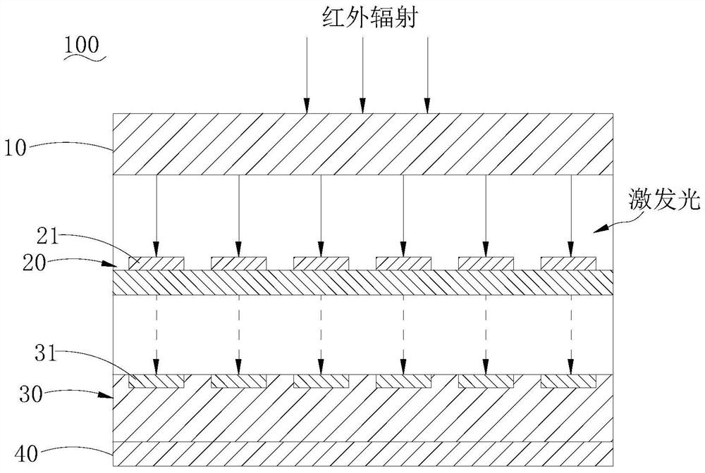
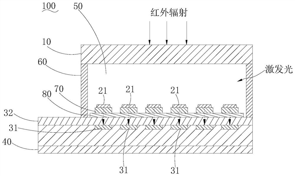
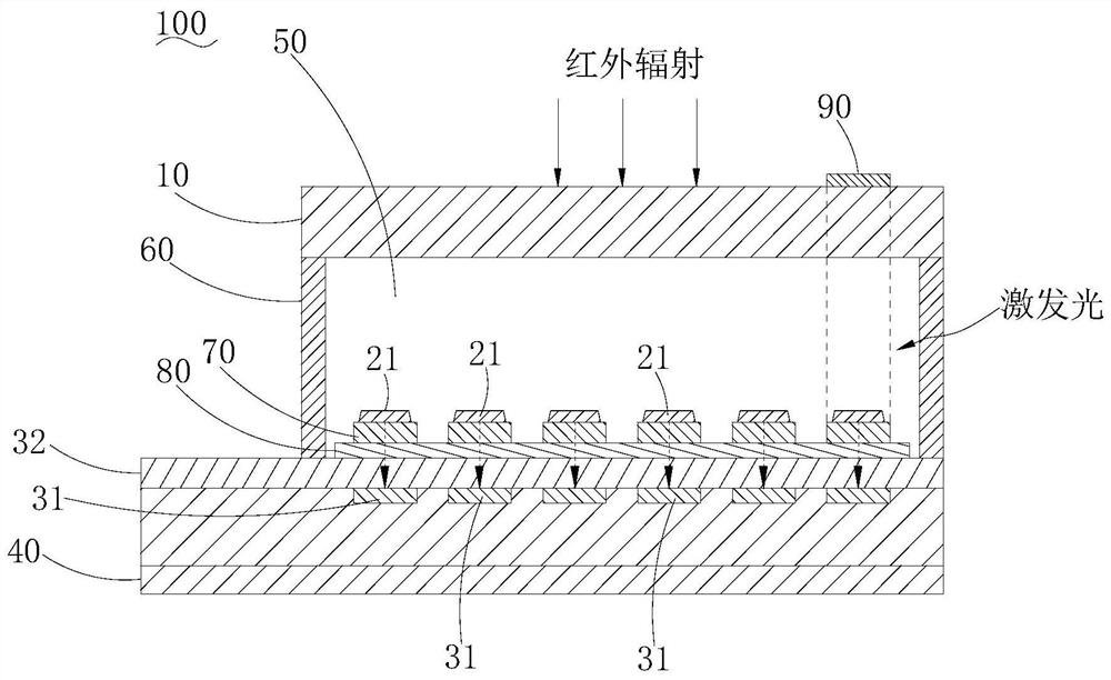
The invention discloses an infrared detection chip and an infrared detector. The infrared detection chip comprises an optical component, an infrared detection array and a photoelectric reading module, the infrared detection array comprises a plurality of infrared detection units which are arranged in an array, and the infrared detection units can emit visible light under the action of exciting light and can change temperature under the action of infrared radiation so as to change the intensity of the visible light. The intensity of the visible light is in negative correlation with the temperature of the infrared detection unit, and the temperature of the infrared detection unit is in positive correlation with the intensity of the received infrared radiation. Photoelectric reading units of the photoelectric reading module are in one-to-one correspondence with the infrared detection units, and the photoelectric reading units are used for detecting the intensity of visible light emitted by the infrared detection units and converting the intensity into electric signals. Therefore, the distribution of infrared radiation can be converted into the light intensity distribution of visible light, and finally, the infrared radiation intensity of different positions and areas can be obtained through the change of electric signals, so that infrared imaging of a heat source is realized.

Description

technical field [0001] The invention relates to the technical field of infrared detection, in particular to an infrared detection chip and an infrared detector. Background technique [0002] At present, uncooled infrared focal plane array technology has been widely used in related fields: in the military, it has become one of the main forces to defend national security; in civilian use, it has been widely used in industry, medical treatment, fire protection and Under video surveillance. [0003] In recent years, several new optical readout uncooled infrared imaging technologies have been developed successively, mainly including dual-material micro-cantilever beam detection technology, Fabry-Perot microcavity infrared detection technology, pyroelectric-optic uncooled infrared detection technology, etc. But they still have some technical problems unresolved. For example, the inherent mechanical noise of the dual-material micro-cantilever detector is not easy to remove, which...

Claims


Application Information

Patent Timeline
Patent Type & Authority Applications(China)
IPC IPC(8): G01J5/10H01L27/146
CPCG01J5/10H01L27/14649
Inventor 王敏金瑛
Owner SOUTH UNIVERSITY OF SCIENCE AND TECHNOLOGY OF CHINA
Learn More