Three-phase circuit measurement and control diagnosis device

A technology of three-phase circuit and diagnosis device, which is applied in measurement device, frequency measurement device, short-circuit test, etc., can solve the problems of insufficient fast circuit diagnosis, easy failure of three-phase circuit, and no recording function.

Pending Publication Date: 2022-03-04
TAIZHOU ANJPOWER EQUIP
View PDF0 Cites 0 Cited by
  • Summary
  • Abstract
  • Description
  • Claims
  • Application Information

AI Technical Summary

Problems solved by technology

[0004] The three-phase circuit measurement and control diagnosis device is not timely and fast enough in the measurement and control processing speed, and does not have the recording function of ba

Method used


Image

  • Three-phase circuit measurement and control diagnosis device
  • Three-phase circuit measurement and control diagnosis device
  • Three-phase circuit measurement and control diagnosis device

Examples


Embodiment 1

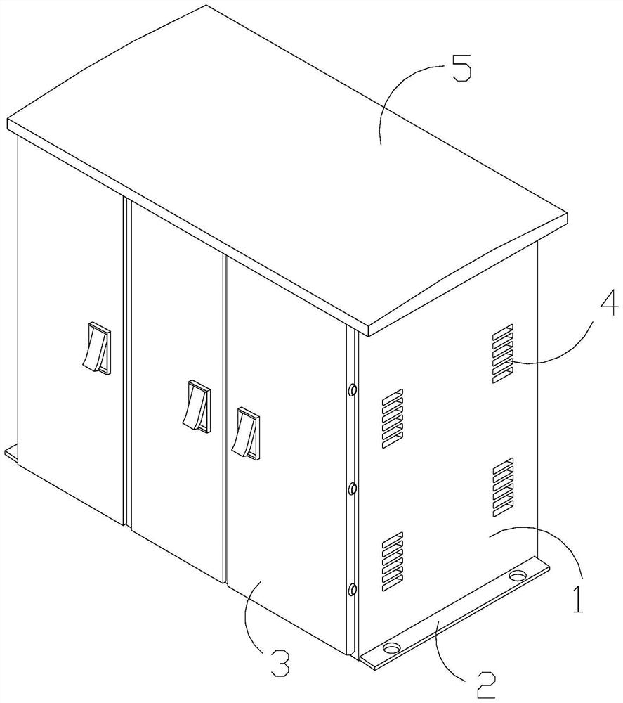
[0029] as attached figure 1 to attach Figure 5 Shown:

[0030] The invention provides a three-phase circuit measurement, control and diagnosis device, which is structured with a circuit box 1, a mounting frame 2, an opening door 3, a heat dissipation port 4, and a top plate 5, and the mounting frame 2 is embedded and connected to the bottom of the outer side of the circuit box 1. position, the opening door 3 is set on the front side of the circuit box 1, the heat dissipation opening 4 is integrated with the circuit box 1 and communicates with each other, and the top plate 5 is fixedly installed above the circuit box 1.

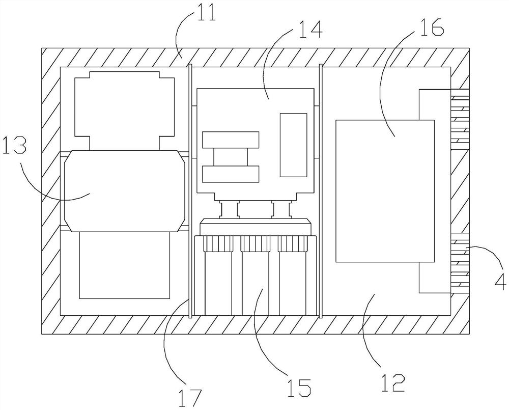
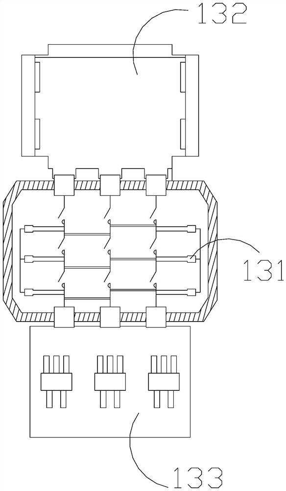
[0031] The circuit box 1 is provided with a box frame 11, an inner chamber 12, a three-phase transformer room 13, a communication module 14, a supercapacitor 15, a data device 16, and a spacer 17, and the installation frame 2 is embedded and connected to the box frame 11. The outer bottom position, the opening door 3 is arranged on the front side of the inn...

Embodiment 2

[0038] as attached Figure 6 to attach Figure 7 Shown:

[0039] Wherein, as a further improvement of the present invention, the communication module 14 is provided with a communication connection terminal 141, a standard communication interface 142, and a multi-rate connection terminal 143, and the communication connection terminal 141 is located at the bottom of the communication module 14 and communicates with each other. The multi-rate connection end 143 is placed on the left side of the middle end of the communication module 14, and the multi-rate connection end 143 is located beside the standard communication interface 142. The standard communication interface 142 and the multi-rate connection end 143 can be connected to multiple The wire terminals are connected, the working power supply voltage is 95-264V AC / DC, and the current frequency conversion is 47Hz-54Hz. The standard communication interface 142 and the multi-rate connection terminal 143 have RS485 standard comm...


PUM


Abstract

The invention discloses a three-phase circuit measurement and control diagnosis device which is structurally provided with a circuit box, a mounting frame, a cover opening door, a heat dissipation opening and a top plate, the mounting frame is fixedly connected to the bottom position of the outer side of the circuit box in an embedded mode, and the cover opening door is arranged on the front side of the circuit box and connected with a three-phase circuit through a three-phase connection opening. The calculation frequency converter can calculate analog quantities such as active power, reactive power, apparent power, power factors and frequency, and is matched with a three-phase circuit to perform current value conversion, so that the electric load can be conveniently adjusted to be in a balanced state, and faults caused by overlarge voltage are effectively avoided; when a three-phase circuit converts a current value, the open-phase protector carries out voltage or current open-phase and phase sequence diagnosis and is matched with an overload detection end to further monitor frequency overrun, so that faults such as short circuit, overload and zero line breaking can be judged and timely disconnection can be carried out, and faults caused by current and voltage changes of the three-phase circuit are reduced.

Description

technical field [0001] The invention belongs to the field of circuit measurement and control, and more specifically relates to a three-phase circuit measurement and control diagnosis device. Background technique [0002] The power grid plays an important role in people's production and life. The detection of the circuit is a link to ensure the stable operation of the power grid. However, there are serious shortages in power parameter monitoring, reactive power control and online monitoring in most areas. Therefore, it is necessary to The three-phase circuit measurement and control diagnosis device plays the role of monitoring and diagnosis in the power grid. [0003] Based on the inventor's discovery above, the existing three-phase circuit measurement and control diagnosis device has the following deficiencies: [0004] The three-phase circuit measurement and control diagnosis device is not timely and fast enough in the measurement and control processing speed, and does not...

Claims


Application Information

Patent Timeline
IPC IPC(8): G01R21/06G01R21/133G01R23/02G01R29/18G01R31/52G01R31/54
CPCG01R21/06G01R21/1331G01R21/002G01R21/003G01R21/005G01R21/006G01R23/02G01R29/18G01R31/52G01R31/54
Inventor 向磊陈义程春玲
Owner TAIZHOU ANJPOWER EQUIP
Why Eureka
Try Eureka