Skeleton type air-blowing composite optical cable

A composite optical cable and skeleton technology, which is applied in the direction of power cables, cables, and optics including optical transmission components, can solve problems such as electric shock, high construction requirements, and high installation costs, and achieve simplified installation procedures, lower laying costs, and lower installation costs. effect of difficulty

Active Publication Date: 2022-03-04
YANGTZE OPTICAL FIBRE & CABLE CO LTD
View PDF6 Cites 0 Cited by
  • Summary
  • Abstract
  • Description
  • Claims
  • Application Information

AI Technical Summary

Problems solved by technology

Under normal circumstances, according to the different laying methods of optical cables, optical cables can be divided into pipeline optical cables, direct buried optical cables, overhead optical cables and underwater optical cables. Pipeline optical cables, direct buried optical cables or underwater optical cables are often used, and there are relatively few applications for overhead optical cables
[0003] However, in the process of laying optical cables, new optical cable lines are often encountered. For the above cases, the usual practice is to re-lay optical cables next to the existing lines , although this can meet the needs of practical applications to a certain extent, but the above-mentioned method has high requirements for construction, and the construction period is long, and the installation cost is also high
At the same time, for direct buried optical cables or duct optical cables, the laying of new lines needs to involve excavation of the ground or road surface, which increases the difficulty of laying new lines to a certain extent.
[0004]In addition, in the laying process of existing optical cables, it is often encountered that power lines or signal lines need to be installed at the same time. Or the signal line is coated in the optical cable at the same time, although this can meet the application requirements to a certain extent, but for this kind of optical cable, it is often necessary to cut off the power in advance when performing subsequent stripping and branching, otherwise there may be a risk of electric shock. risk, causing serious safety accidents; moreover, for optical cables with signal lines and power lines installed at the same time, the power lines and signal lines themselves are not convenient for air-blowing laying, and the twisting difficulty in the air-blowing optical cable structure is also relatively large, which leads to Existing optical cables are difficult to meet the needs of practical applications

Method used


Image

  • Skeleton type air-blowing composite optical cable
  • Skeleton type air-blowing composite optical cable
  • Skeleton type air-blowing composite optical cable

Examples


preparation example Construction

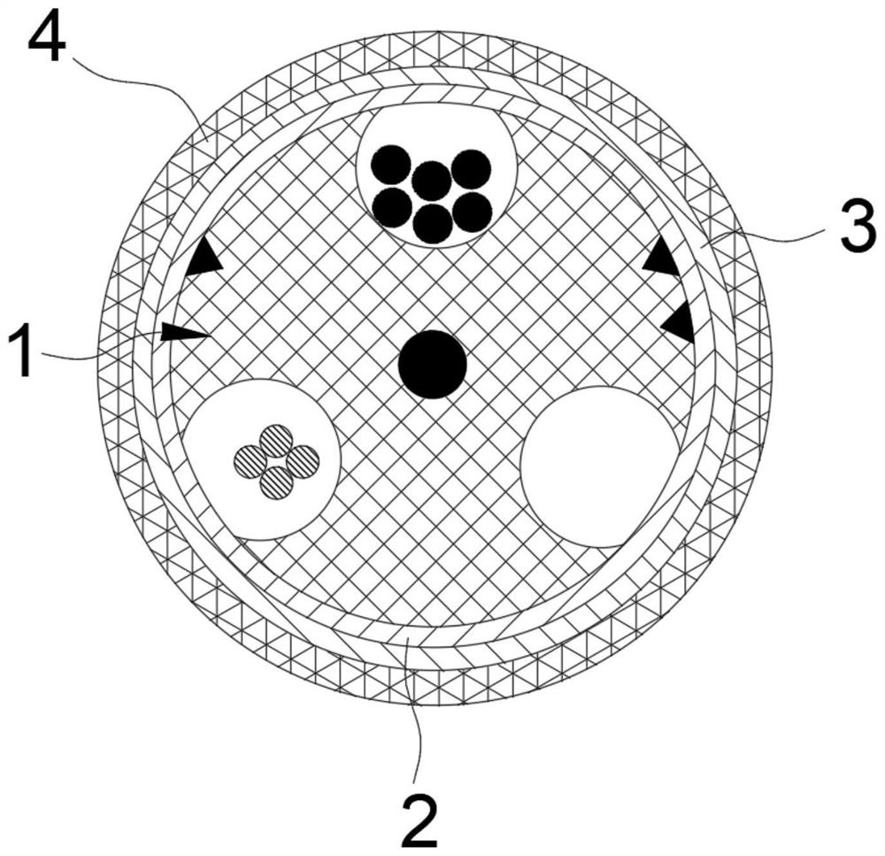
[0053] In the preparation process of the composite optical cable, after the laying of the cable in the first skeleton groove 101 is completed, a water blocking layer 2 is preferably formed on the outer periphery of the skeleton 1, and a reinforcing layer and / or The armor layer 3 accurately encapsulates the cables in the first skeleton slot 101 to ensure the water resistance and damage resistance of the composite optical cable in practical applications. In a preferred embodiment, the water-blocking layer 2 is formed by winding the water-blocking tape on the outer periphery of the skeleton 1 in turn, the reinforcement layer is formed by winding and covering the outer periphery of the water-blocking layer in sequence with moisture-proof aluminum tape, and the armor layer 3 is formed by FRP tape in turn twisted. When the water-blocking layer 2 , the reinforcement layer and the armor layer 3 are provided at the same time, the reinforcement layer is arranged between the water-block ...

Embodiment 1

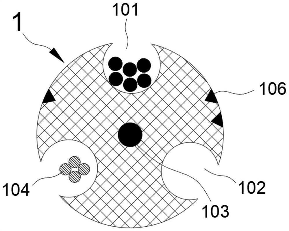
[0057] In this embodiment, in addition to the above-mentioned basic settings, the structure of the composite optical cable is also provided with a skeleton reinforcement 103 in the middle of the skeleton 1. The skeleton reinforcement 103 is a single-core or multi-core reinforcement wire, which extends longitudinally along the skeleton 1. According to actual needs, it can be made of metal materials such as steel wires and iron wires, or it can be made of hard non-metallic materials.

[0058] In actual operation, the skeleton 1 is formed by continuous extrusion molding on the periphery of the skeleton reinforcement 103, and then other corresponding structures are arranged in the skeleton 1 and outside the skeleton, and finally formed such as figure 1 Composite cable structure shown in .

Embodiment 2

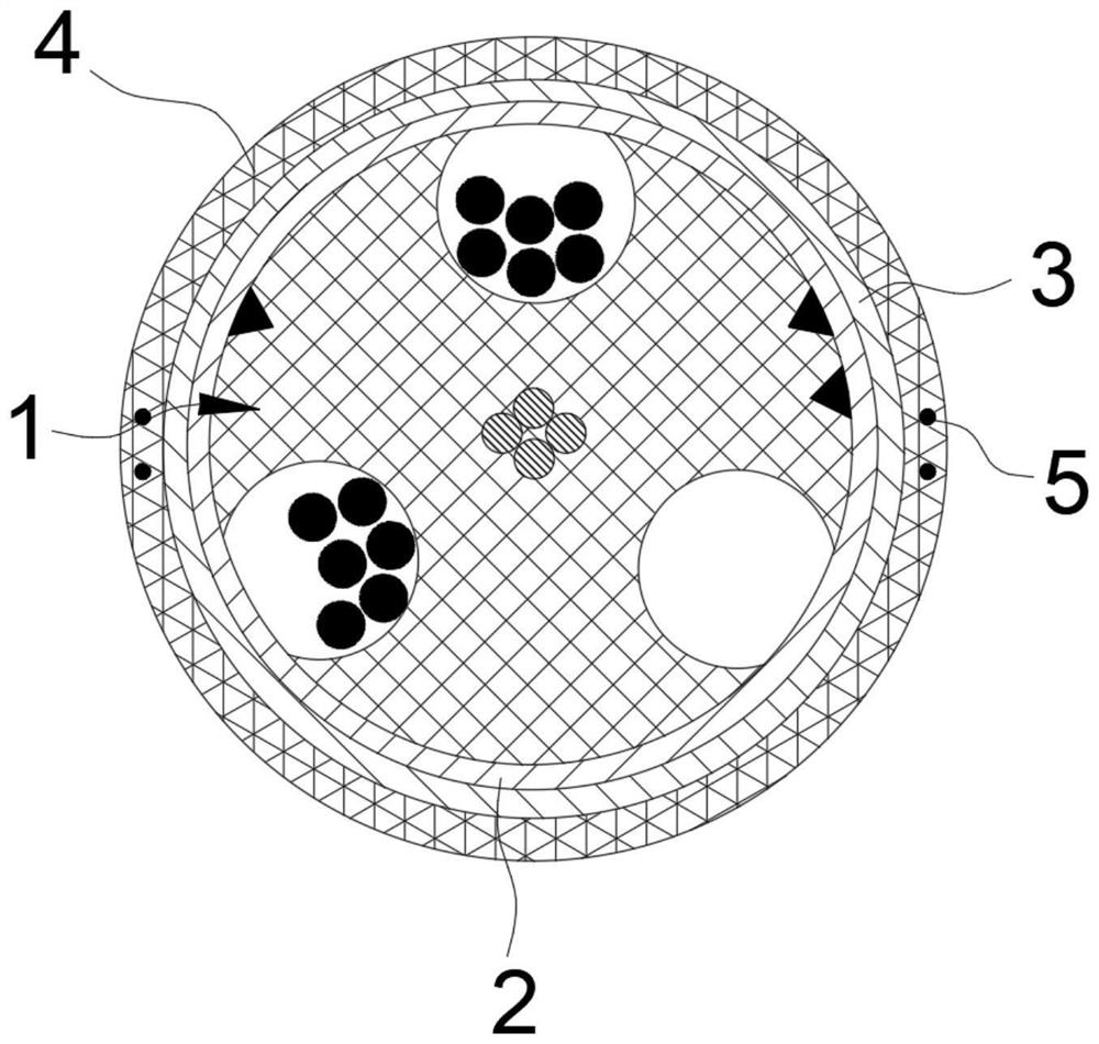
[0060] In this embodiment, the difference between the structure of the composite optical cable and the above-mentioned basic structure is that: the middle part of the frame 1 is covered with a power line 104. At this time, the power line 104 does not need to be arranged in the first frame groove 101, and Corresponding signal lines and optical fiber units can be correspondingly accommodated.

[0061] Through the above-mentioned setting of the power line 104, the separation of the power line and other cables can be fully realized, and it is ensured that when the fiber optic cable is branched and the air blows the fiber optic cable, there is no need to cut off the power to the composite fiber optic cable, ensuring the reliability of the corresponding machine room, and minimizing Composite optical cable air blowing operation or optical fiber divergence will affect the work of other cables and equipment, and improve the application reliability of composite optical cable.

[0062] I...


PUM

PropertyMeasurementUnit
surface roughnessaaaaaaaaaa
diameteraaaaaaaaaa
diameteraaaaaaaaaa

Abstract

The invention discloses a skeleton type air-blowing composite optical cable, which belongs to the technical field of optical cables and is characterized in that at least one first skeleton groove capable of correspondingly laying an optical fiber unit or a related cable in the forming process of the composite optical cable can be formed in the periphery of a skeleton by optimally designing the structural form of the skeleton in the skeleton type optical cable; and at least one vacant second framework groove is formed in the periphery of the framework, so that a corresponding reserved groove channel can be formed in the composite optical cable, and convenience is provided for subsequent arrangement of newly-added cables. The skeleton type air-blowing composite optical cable is simple in structure and convenient to prepare, at least one pipeline used for air-blowing laying of the air-blowing optical cable can be formed after the optical cable is laid, convenience is provided for subsequent arrangement of corresponding optical cables in an air-blowing laying mode, the situation that a new optical cable is laid beside the composite optical cable again is avoided, and the production efficiency is improved. The process of laying the newly added optical cable is simplified, the cost is saved, the urban landscape after the composite optical cable is laid is improved, and the composite optical cable has good application prospect and popularization value.

Description

technical field [0001] The invention belongs to the technical field of optical cables, and in particular relates to a skeleton type air-blown composite optical cable. Background technique [0002] With the development of communication technology, people have higher and higher requirements for communication quality, and higher and higher requirements are also put forward for optical cables used in optical fiber communication. Under normal circumstances, according to the different laying methods of optical cables, optical cables can be divided into pipeline optical cables, direct buried optical cables, overhead optical cables and underwater optical cables. Pipeline optical cables, direct buried optical cables or underwater optical cables are often used, and there are relatively few applications for overhead optical cables. [0003] However, in the process of laying optical cables, it is often encountered that new optical cable lines are added. For the above cases, the usual p...

Claims


Application Information

Patent Timeline
Patent Type & Authority Applications(China)
IPC IPC(8): H01B11/22H01B9/00H01B7/17H01B7/18G02B6/44
CPCH01B11/22H01B9/005H01B7/17H01B7/18G02B6/4404G02B6/4429G02B6/4434G02B6/443
Inventor 刘为马波阎浩
Owner YANGTZE OPTICAL FIBRE & CABLE CO LTD
Why Eureka
Try Eureka