
Die bonder

A crystal bonding machine, a crystal bonding technology, applied in the direction of conveyor objects, semiconductor/solid-state device manufacturing, electrical components, etc., can solve problems such as low bonding efficiency, affecting the chip placement accuracy of the bonding rate, and slow bonding speed. To achieve the effect of improving efficiency

Active Publication Date: 2022-03-04
SHEN ZHEN TALUER TECH CO LTD
View PDF6 Cites 0 Cited by
  • Summary
  • Abstract
  • Description
  • Claims
  • Application Information

AI Technical Summary

Problems solved by technology

During the entire die bonding process, the die bonding swing arm needs to rotate and move downwards and upwards to fix a chip to a specified position on the pad. Such a die bonding machine has slow die bonding speed and low die bonding efficiency. Die bonding 20000 pieces / h; and using such a die bonding machine, when picking up a chip on a large-sized wafer tray, or when placing the picked-up chip on a large-sized pad by the die-bonding swing arm, it is necessary to Increasing the length of the die-bonding swing arm can pick up or place the chip smoothly, and increasing the length of the die-bonding swing arm will undoubtedly increase the weight of the die-bonding swing arm, and increasing the weight of the die-bonding swing arm will definitely increase the movement of the die-bonding swing arm. The amount of inertia will reduce the stability of the die-bonding swing arm movement, and ultimately affect the speed of die-bonding and the accuracy of wafer placement

Method used


Image

  • Die bonder
  • Die bonder
  • Die bonder

Examples


Embodiment Construction

[0038]In order to make the purposes, technical solutions and advantages of the embodiments of the present application clearer, the technical solutions in the embodiments of the present application will be clearly and completely described below in conjunction with the drawings in the embodiments of the present application. Obviously, the described embodiments It is a part of the embodiments of this application, but not all of them. Based on the embodiments in the present application, all other embodiments obtained by persons of ordinary skill in the art without making creative efforts belong to the protection scope of the present application.

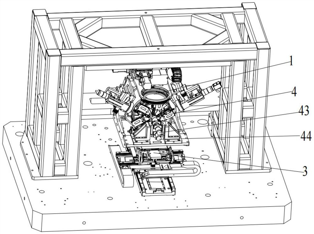
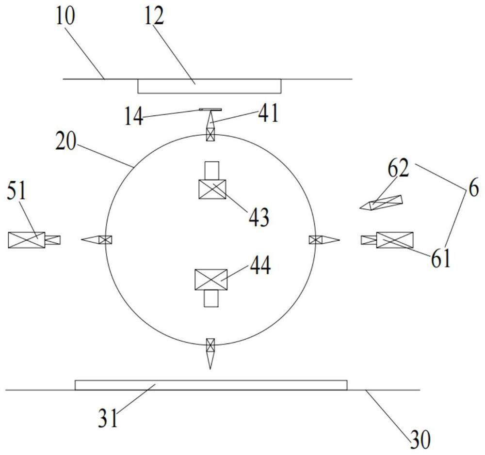
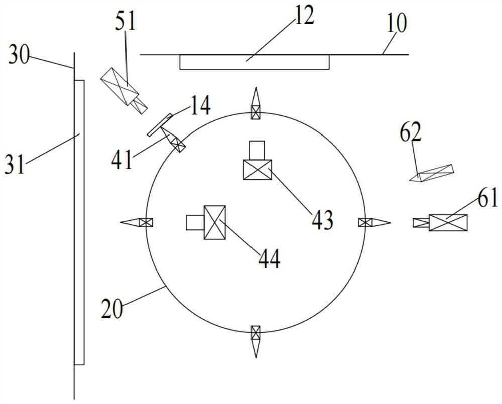
[0039] Such as Figure 1-Figure 12 As shown in , the present application proposes a crystal bonding machine, which includes: a crystal supply mechanism 1, which includes a crystal element ring 11, one side surface of the crystal element ring 11 is parallel to the first plane 10, and the The crystal element ring 11 is provided with a cry...


PUM


Abstract

The invention provides a die bonder which comprises the components of a wafer supply mechanism which comprises a wafer ring which is provided with a wafer supply position for supplying a wafer; the rotating mechanism comprises a rotating disc, the rotating disc is rotationally arranged on one side of the wafer ring, and the rotating plane of the rotating disc is perpendicular to the wafer ring; the bearing mechanism comprises a substrate, the substrate is arranged on one side of the turntable, a wafer fixing position for fixing a wafer is arranged on the substrate, and the substrate is perpendicular to the rotating plane of the turntable; the pick-and-place mechanism comprises a wafer suction nozzle, and the wafer suction nozzle is arranged on the turntable and used for sucking the wafer; according to the die bonder provided by the invention, two actions of die taking and die bonding can be realized in one period of rotation of the turntable, and the die bonding efficiency can be improved.

Description

technical field [0001] The present application relates to the technical field of crystal bonding, in particular to a high-precision and high-speed crystal bonding machine. Background technique [0002] The crystal-bonding process of the existing crystal-bonding machine is as follows: the thimble mechanism lifts the specified wafer from the wafer film, and then the crystal-bonding swing arm rotates to the top of the specified wafer (the crystal-bonding swing arm generally rotates 180°, One rotation cycle takes 180ms), first move down to pick up the wafer, then move up to lift the wafer, and then rotate to transport the wafer to the designated bonding position on the pad. During the entire die bonding process, the die bonding swing arm needs to rotate and move downwards and upwards to fix a chip to a specified position on the pad. Such a die bonding machine has slow die bonding speed and low die bonding efficiency. Die bonding 20000 pieces / h; and using such a die bonding mach...

Claims


Application Information

Patent Timeline
Patent Type & Authority Applications(China)
IPC IPC(8): H01L21/67H01L21/677H01L21/68
CPCH01L21/67144H01L21/67742H01L21/681
Inventor 曾逸张维伦吴勇
Owner SHEN ZHEN TALUER TECH CO LTD
Learn More