Novel biological foodstuff blending device

A biological and food material technology, applied to mixers with rotating stirring devices, transportation and packaging, mixer accessories, etc., can solve problems such as simple structure, low work efficiency, and high labor costs

Pending Publication Date: 2022-03-08
熊小天
View PDF10 Cites 2 Cited by
  • Summary
  • Abstract
  • Description
  • Claims
  • Application Information

AI Technical Summary

Problems solved by technology

[0005] In order to overcome the shortcomings of the existing blending device, such as simple structure, high labor cost and low work efficiency, the purpose of the present invention is to provide a new type of biological food blending device capable of intermittent feeding, automatic discharging and automatic pushing

Method used


Image

  • Novel biological foodstuff blending device
  • Novel biological foodstuff blending device
  • Novel biological foodstuff blending device

Examples


Embodiment 1

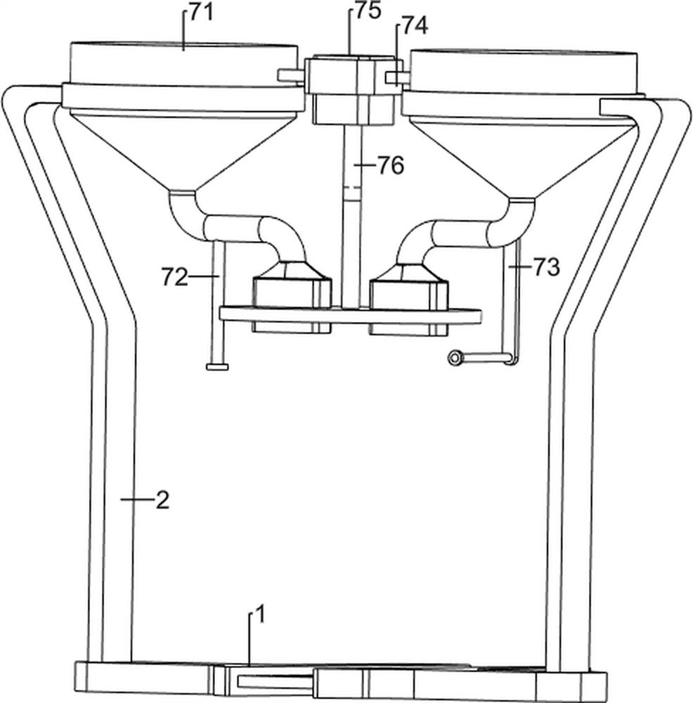
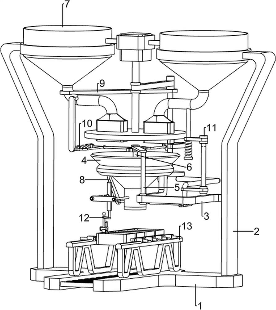
[0031] A novel biological food preparation device, such as figure 1 , figure 2 and image 3 As shown, it includes a first support plate 1, a first support frame 2, a first support rod 3, a stirring frame 4, a second support rod 5, an agitator 6, an intermittent feeding mechanism 7, a discharge box 71, a third Support rod 72, the second support frame 73, the first fixed frame 74, motor 75, rotating blanking rack 76, opening and closing mechanism 8, rotating post 81, opener 82, the first torsion spring 83, long plate 84, rotating Mechanism 9, first connecting fixed plate 91, rotating shaft 92, transmission assembly 93, cam 94, ball block 95, stirring driving mechanism 10, rack bar 101, stabilizing bar 102, first spring 103, gear 104, pressing mechanism 11 , the second fixed frame 111, the second spring 112, the presser 113, the pushing mechanism 12, the third fixed frame 121, the long plate frame 122, the third spring 123, the pushing frame 124, the pushing block 125, the sec...

Embodiment 2

[0036] On the basis of Example 1, such as figure 1 and Figure 4 , Figure 5 , Figure 6 and Figure 7 As shown, the bottom of the discharge box 71 on the left side is provided with a first connecting fixed plate 91, and the inner side of the first connecting fixed plate 91 is rotated to be provided with a rotating shaft 92, and a transmission is connected between the rotating shaft 92 top and the rotating blanking frame 76. Assembly 93, transmission assembly 93 is made up of two belt pulleys and a belt, and a belt pulley is connected on the rotating unloading frame 76, and another belt pulley is connected on the rotating shaft 92, and belt is connected between two pulleys, and rotating shaft 92 bottoms are provided with The cam 94 and the bottom of the rotating shaft 92 are provided with a ball block 95 .

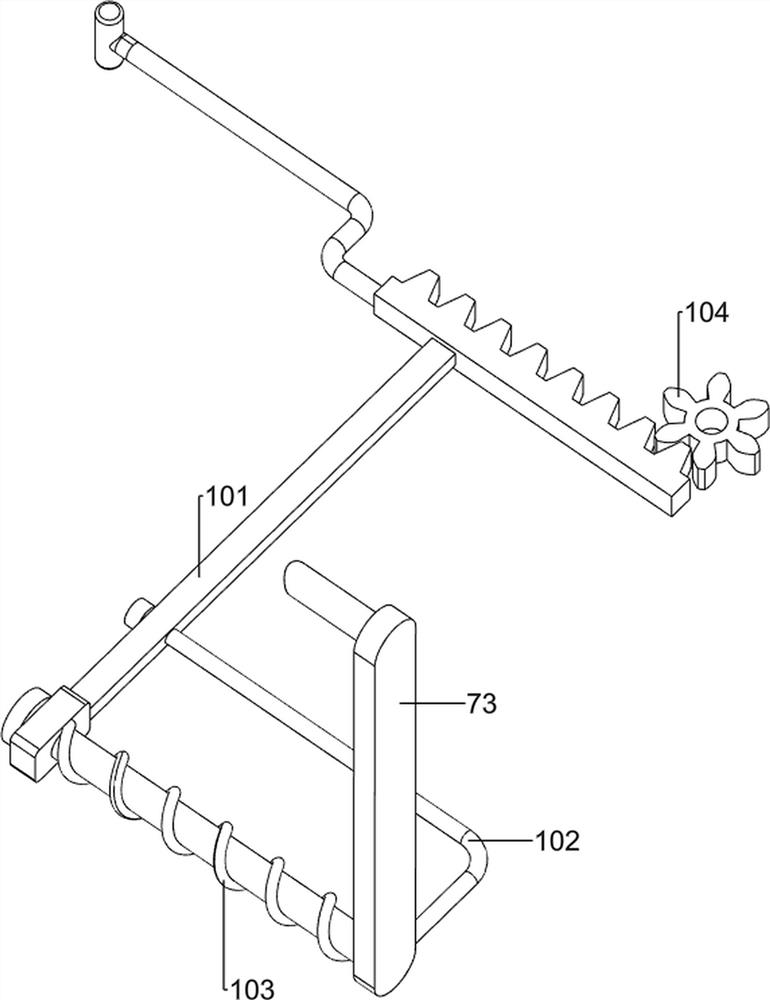
[0037] The second support frame 73 is provided with a rack bar 101 slidingly, and the rack bar 101 cooperates with the cam 94. The second support frame 73 is provided ...


PUM


Abstract

The invention relates to a blending device, in particular to a novel biological foodstuff blending device. The novel biological foodstuff blending device provided by the invention can realize intermittent feeding, automatic discharging and automatic pushing. A novel biological food blending device comprises a first supporting plate, two first supporting frames, a first supporting rod, a stirring frame, a second supporting rod, a stirrer, an intermittent discharging mechanism, an opening and closing mechanism and a charging production line, the two first supporting frames are arranged on the top of the first supporting plate, and the first supporting rod is arranged on the first supporting frame on one side; a stirring frame is arranged on the inner sides of the first supporting rods, a second supporting rod is arranged on the inner sides of the first supporting rods, a stirrer is rotationally arranged on the second supporting rod, the stirrer is matched with the stirring frame, and an intermittent discharging mechanism is connected between the two first supporting rods. By arranging the intermittent discharging mechanism, raw materials and water can intermittently flow into the stirring frame through operation of the intermittent discharging mechanism, and the purpose of automatic intermittent discharging is achieved.

Description

technical field [0001] The invention relates to a compounding device, in particular to a novel biological food material compounding device. Background technique [0002] In the production process of new biological food, it is often necessary to mix two kinds of raw materials to meet the production requirements of biological food. The structure of the existing mixing device for biological food is relatively simple, and most of them can only achieve automatic mixing of raw materials. Whether it is feeding or discharging, most of the existing blending devices require manual operation, which is time-consuming and laborious, and requires a lot of labor costs, which will affect the production and processing efficiency of biological food. [0003] Patent application CN210169014U, the publication date is 2020.03.24, discloses a feed blending device for aquatic products, including a box, a feed cylinder, a horizontal plate, a crushing mechanism, a stirring mechanism, a first transmis...

Claims


Application Information

Patent Timeline
Patent Type & Authority Applications(China)
IPC IPC(8): B01F27/80B01F35/30B01F35/31B01F35/41B01F35/42B01F35/43B01F35/50B01F35/71B01F35/75B01F23/80B01F35/33
Inventor 熊小天
Owner 熊小天
Why Eureka
Try Eureka