Energy-saving and environment-friendly kitchen waste treatment device
A waste treatment device, energy saving and environmental protection technology, applied in biomass post-processing, biomass pretreatment, biochemical cleaning devices, etc.
- Summary
- Abstract
- Description
- Claims
- Application Information
AI Technical Summary
Problems solved by technology
Method used
Image
Examples
Embodiment 1
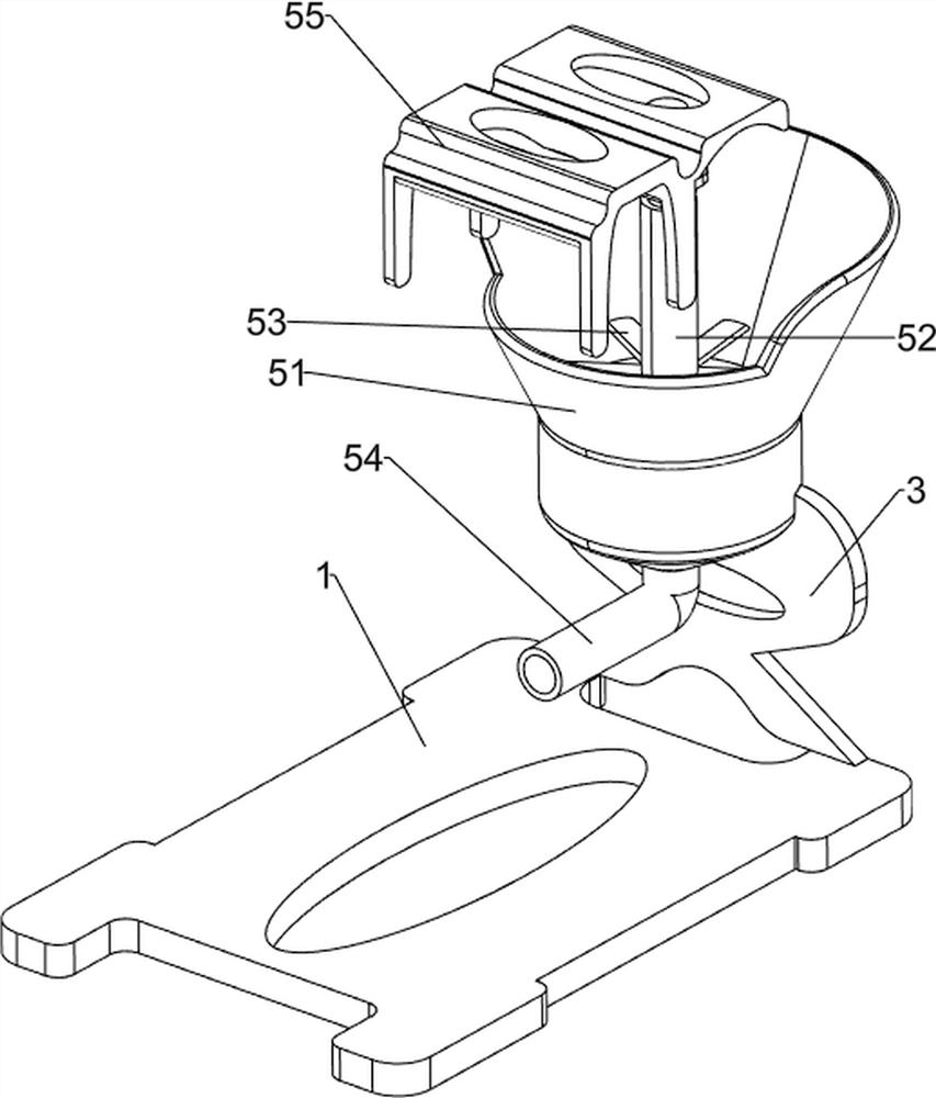
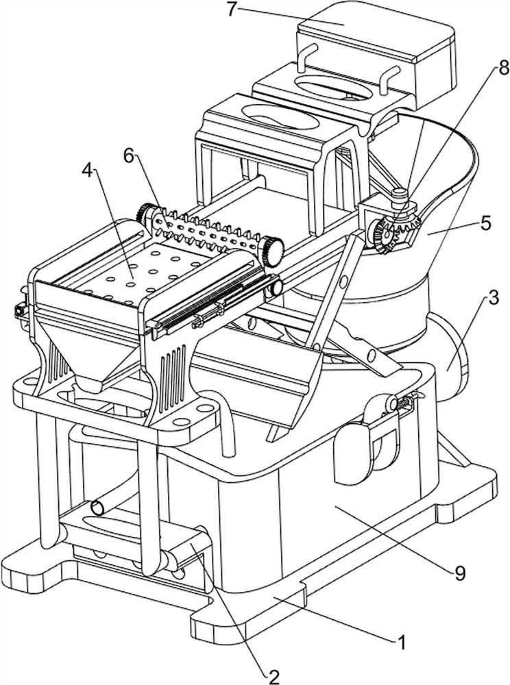
[0072] An energy-saving and environment-friendly dining kitchen waste treatment device, such as figure 1 As shown, it includes a base 1, a support block 2, a first fixed frame 3, a filter mechanism 4 and a stirring mechanism 5, a support block 2 is provided on the front side of the base 1, and a first fixed frame 3 is provided on the rear side of the base 1. A filter mechanism 4 is provided on the support block 2 , and a stirring mechanism 5 is provided on the top of the first fixing frame 3 , and the stirring mechanism 5 is connected with the filter mechanism 4 .
[0073] First, people pour food waste into the filter mechanism 4, the filter mechanism 4 separates the solid and liquid of the food waste, and then people push the solid waste in the filter mechanism 4 backward, and then the filter mechanism 4 is partially operated, and people stop pushing the garbage at the same time , the filter mechanism 4 partly operates to make the solid waste continue to move backward, and th...
Embodiment 2
[0075] On the basis of Example 1, such as figure 2 and image 3 As shown, the filter mechanism 4 includes a first support frame 41, a water frame 42, a filter frame 43, a second fixed frame 44, a drum 45 and a conveyor belt 46, and the inner side of the upper part of the support block 2 is provided with the first support frame 41, the first support The top of the frame 41 is provided with a filter frame 43, the bottom of the filter frame 43 is provided with a water frame 42, the upper part of the rear side of the filter frame 43 is provided with a second fixed frame 44, and the upper side of the second fixed frame 44 is rotatably connected between the left and right sides. Two cylinders 45, the cylinder 45 on the front and back sides is wound with conveyer belt 46.
[0076] People pour the kitchen waste on the top of the filter frame 43, and the filter frame 43 filters the food waste, and the solid garbage stays on the top of the filter frame 43, while the liquid garbage flo...
Embodiment 3
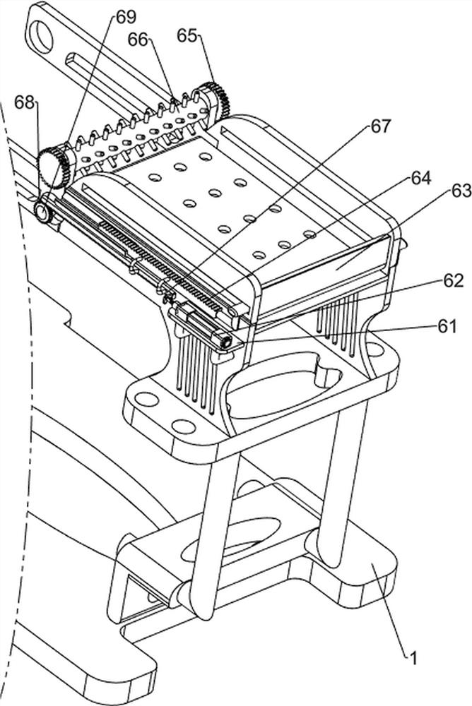
[0080] On the basis of Example 2, such as figure 1 , Figure 4 , Figure 5 , Figure 6 and Figure 7 Shown, also include pushing mechanism 6, and pushing mechanism 6 includes first fixed block 61, cylinder 62, push block 63, first rack 64, first one-way gear 65, rolling hair brush 66, second rack 67. The second one-way gear 68 and the second rotating shaft 69, the left front part of the filter frame 43 is provided with a first fixed block 61, the top of the first fixed block 61 is provided with a cylinder 62, and the upper part of the filter frame 43 slides between the left and right sides is connected with a push block 63, the left and right sides of the bottom of the push block 63 are provided with a first rack 64, the first rack 64 is slidingly connected with the filter frame 43, and the outside of the first rack 64 is provided with a second rack 67, The second rack 67 is slidably connected with the filter frame 43, the cylinder 62 is connected with the second rack 67 o...
PUM
 Abstract
Description
Claims
Application Information
 - R&D
- Intellectual Property
- Life Sciences
- Materials
- Tech Scout
- Unparalleled Data Quality
- Higher Quality Content
- 60% Fewer Hallucinations
Browse by: Latest US Patents, China's latest patents, Technical Efficacy Thesaurus, Application Domain, Technology Topic, Popular Technical Reports.
© 2025 PatSnap. All rights reserved.Legal|Privacy policy|Modern Slavery Act Transparency Statement|Sitemap|About US| Contact US: help@patsnap.com


