
Intelligent guniting robot

A robot and spraying technology, which is applied in the direction of manipulators, spraying devices, manufacturing tools, etc., can solve problems such as the inability to keep the spray gun vertical, many safety hazards, and complicated procedures.

Pending Publication Date: 2022-03-08
山东泽明能源科技有限公司
View PDF8 Cites 0 Cited by
  • Summary
  • Abstract
  • Description
  • Claims
  • Application Information

AI Technical Summary

Problems solved by technology

[0004] The purpose of the present invention is to provide an intelligent spraying robot, which has the advantages of being convenient for on-site construction, improving the spraying efficiency, and ensuring the spraying effect. Scaffolding and other procedures are complicated, there are many safety hazards, the slurry has a high rebound rate, the spraying is uneven, and manual operation cannot keep the spray gun perpendicular to the sprayed surface, etc.

Method used


Image

  • Intelligent guniting robot
  • Intelligent guniting robot

Examples


Embodiment 1

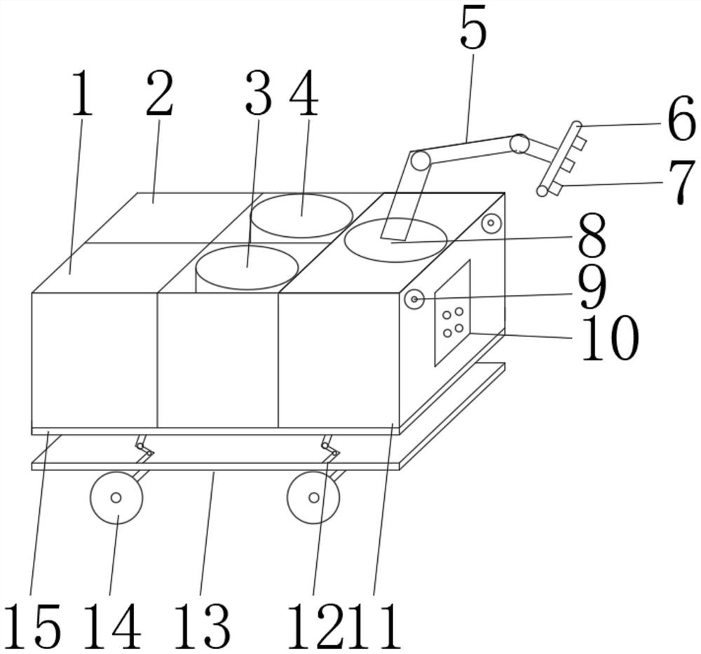
[0029]An intelligent spraying robot, including other storage area 1, spare parts storage area 2, slurry box 11 and base plate 13, a supporting plate 15 is installed above the base plate 13, and a lifting device 12 is evenly installed between the base plate 13 and the supporting plate 15 , the lifting device 12 can realize the lifting of the equipment to be suitable for spraying operations at different heights, and is suitable for spraying heights of 0-4.5m; Scissor type, guide rail type and other forms, the power source can be hydraulic, pneumatic, electric, etc., one end of the pallet 15 is installed with a slurry box 11, and the inside of the slurry box 11 is equipped with precise positioning equipment, and it is connected with the on-site positioning system. Compatible to realize the precise positioning of the spraying robot. The agitator can be installed inside the slurry box 11 according to the slurry mixing requirements for manual mixing or automatic mixing. Before the sl...

Embodiment 2

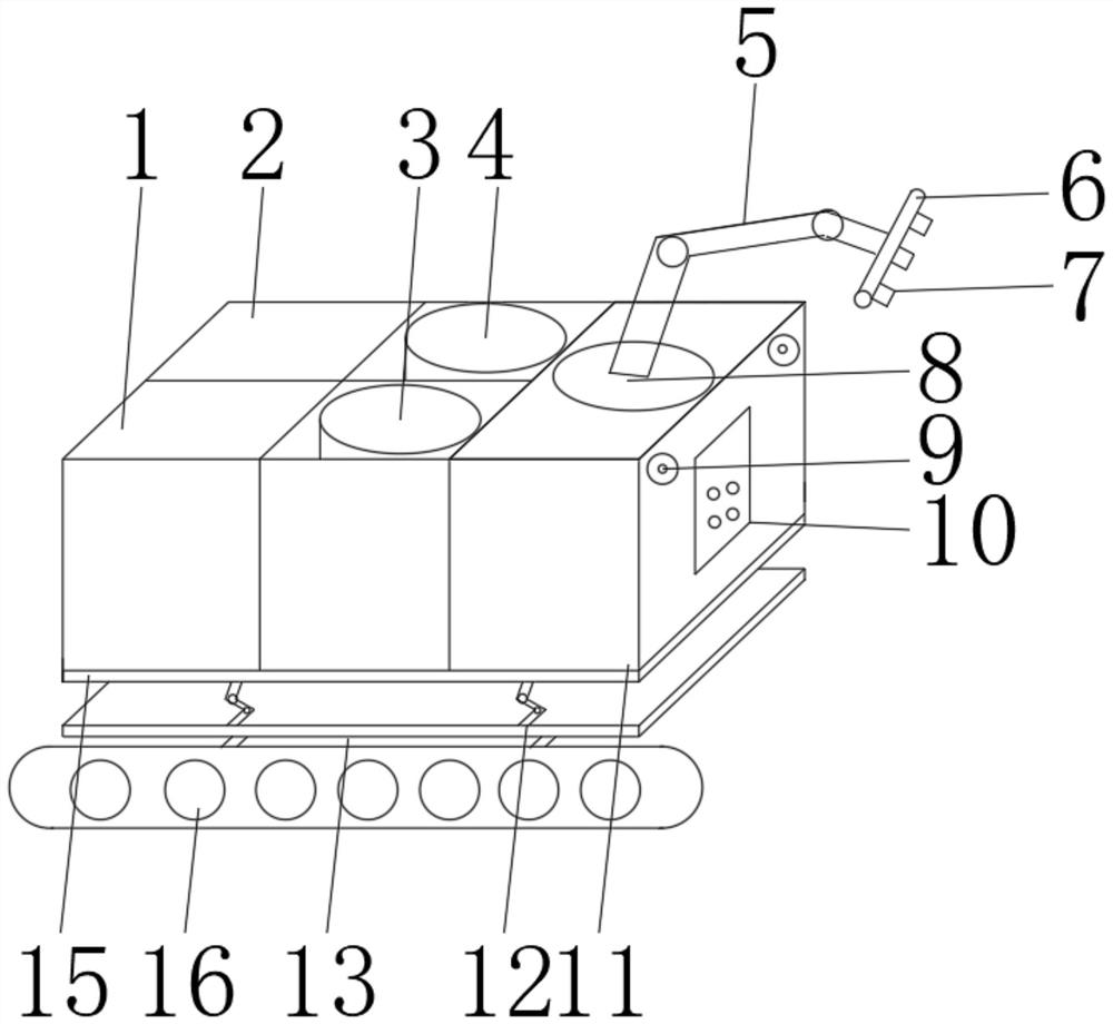
[0032] An intelligent spraying robot, including other storage area 1, spare parts storage area 2, slurry box 11 and base plate 13, a supporting plate 15 is installed above the base plate 13, and a lifting device 12 is evenly installed between the base plate 13 and the supporting plate 15 , the lifting device 12 can realize the lifting of the equipment to be suitable for spraying operations at different heights, and is suitable for spraying heights of 0-4.5m; Scissor type, guide rail type and other forms, the power source can be hydraulic, pneumatic, electric, etc., one end of the pallet 15 is installed with a slurry box 11, and the inside of the slurry box 11 is equipped with precise positioning equipment, and it is connected with the on-site positioning system. Compatible to realize the precise positioning of the spraying robot. The inside of the slurry box 11 can be installed with a mixer according to the slurry mixing requirements, for manual mixing or automatic mixing. Ther...


PUM


Abstract

The intelligent guniting robot comprises an other storage area, a spare part storage area, a slurry box and a bottom plate, a supporting plate is installed above the bottom plate, the slurry box is installed at one end of the supporting plate, and a standby material B area and a standby material A area are arranged on one side of the slurry box; other storage areas and spare part storage areas are arranged on the sides, away from the slurry box, of the standby material B area and the standby material A area, walking wheels are installed on the surface of the bottom end of the bottom plate, a rotating disc is rotatably installed on the surface of the top end of the slurry box, a mechanical arm is movably installed on the rotating disc, and a spray gun is installed at the end, away from the rotating disc, of the mechanical arm; and spray heads are uniformly mounted on the spray gun. The method has the advantages that site construction is facilitated, the guniting efficiency is improved, and the guniting effect is ensured.

Description

technical field [0001] The invention relates to the technical field of mine engineering, in particular to an intelligent spraying robot. Background technique [0002] At present, the shotcrete technology used in tunnel and mine engineering is widely used, and is widely used in the shotcrete support of tunnels and mines, the sealing of surrounding rocks and the sealing of goafs. However, the traditional artificial spraying process often has many dusts on the construction site, poor environment, complicated procedures such as scaffolding, many safety hazards, high rebound rate of slurry, uneven spraying, and manual operation cannot keep the spray gun perpendicular to the sprayed surface. And other issues. Moreover, the automation and intelligence of spraying cannot be realized, the high coordination of spraying frequency and slurry reaction, the self-moving spraying construction, automatic identification, scene scanning and other functions cannot be realized, resulting in poo...

Claims


Application Information

Patent Timeline
IPC IPC(8): B05B13/04B05B13/02B05B15/25B05B15/62B05B15/00B05B12/08B25J11/00
CPCB05B13/0431B05B13/0278B05B15/25B05B15/62B05B15/00B05B12/08B25J11/0075
Inventor 李鑫郭鹏王涛牛金华
Owner 山东泽明能源科技有限公司
Learn More