A clamping device and method for a wind power gearbox case cover

A wind power gearbox and clamping device technology, which is applied in the direction of positioning devices, clamping, and final product manufacturing, can solve the problems of reduced processing production efficiency, high production costs, and a lot of auxiliary time for assembly and calibration, etc., to save The process of installation and adjustment, the reduction of equipment cost, and the effect of ingenious structural design

Active Publication Date: 2022-05-17
德力佳传动科技(江苏)股份有限公司
View PDF0 Cites 0 Cited by
  • Summary
  • Abstract
  • Description
  • Claims
  • Application Information

AI Technical Summary

Problems solved by technology

[0003] In the manufacturing process of the wind power gearbox, the milling of the wind power gearbox cover is the first finishing process after the rough machining. For the traditional vertical machining center, it can only be based on the difference between the two bearing holes in the diameter direction. In order to correct the line connecting the centers of the two bearing holes parallel to the X-axis of the machine tool, and use one bearing hole as the programming zero point to mill the box cover surface and process the threaded holes and positioning pin holes on the box surface, however, this correction method requires many times Adjust the position of the bearing hole on the Y-axis of the machine tool so that the line connecting the centers of the two bearing holes is parallel to the X-axis of the machine tool, resulting in more auxiliary time for assembly and calibration than the normal processing time of the part, reducing the processing efficiency. In addition, the current In the prior art, the distance between the clamping devices is fixed, which can only be used for the milling process of a wind power gearbox cover, and its versatility is poor. When producing the case covers with different sizes and center distances, multiple clamping devices need to be equipped. Frequent replacement is time-consuming and laborious, and the production cost is high

Method used


Image

  • A clamping device and method for a wind power gearbox case cover
  • A clamping device and method for a wind power gearbox case cover
  • A clamping device and method for a wind power gearbox case cover

Examples


Embodiment Construction

[0032]The technical solutions in the embodiments of the present invention will be clearly and completely described below in conjunction with the accompanying drawings in the embodiments of the present invention. Obviously, the described embodiments are only some of the embodiments of the present invention, not all of them.

[0033] In describing the present invention, it should be understood that the terms "upper", "lower", "front", "rear", "left", "right", "top", "bottom", "inner", " The orientation or positional relationship indicated by "outside", etc. is based on the orientation or positional relationship shown in the drawings, and is only for the convenience of describing the present invention and simplifying the description, rather than indicating or implying that the referred device or element must have a specific orientation, so as to Specific orientation configurations and operations, therefore, are not to be construed as limitations on the invention.

[0034] see F...


PUM


Abstract

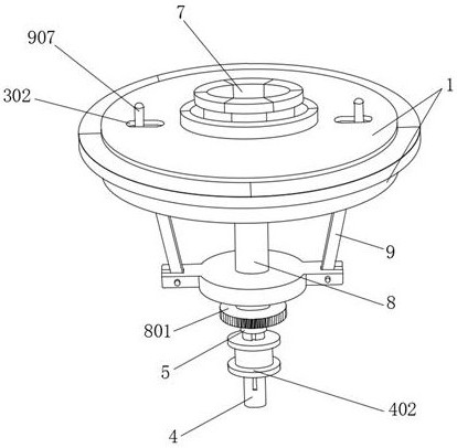
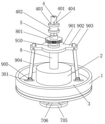
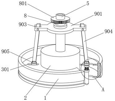
The invention discloses a clamping device and method for a case cover of a wind power gearbox, comprising an external assembly seat, an internal assembly seat is arranged in the center of the external assembly seat, and two connections are connected between the external assembly seat and the internal assembly seat. An adjusting disc, the center of the internal assembly seat is rotatably embedded with a main shaft, the outer side of the main shaft is sleeved with a positioning sleeve, and the part of the positioning sleeve located in the internal assembly seat is fixedly connected with a clamping platform, through the main shaft, The setting of the rotating disk, guide rod, clamping block, and containing box is driven by the external rotary drive device to rotate the main shaft, the main shaft drives the rotating disk to rotate, and the chute on the rotating disk drives the guide rod to slide along the guide groove, so that multiple guides can be adjusted synchronously. The rod moves outward or inward, so that each clamping block can be merged or separated. When the arc-shaped grooves of all clamping blocks fit with the inner wall of the bearing hole of the wind power gearbox case cover, it can form a bearing hole with the same radius as the bearing hole. nearly circular structure.

Description

technical field [0001] The invention relates to the technical field of clamping equipment, in particular to a clamping device and method for a wind power gearbox case cover. Background technique [0002] The gearbox in the wind turbine is an important mechanical component. Its main function is to transmit the power generated by the wind rotor to the generator under the action of the wind and make it obtain a corresponding speed. Usually the speed of the wind rotor is very low, far away If it cannot reach the speed required by the generator for power generation, it must be realized through the speed-up effect of the gear pair of the gearbox, so the gearbox is also called a speed-up gearbox. According to the overall layout requirements of the unit, sometimes it will be directly connected to the hub of the wind wheel The connected transmission shaft and the gearbox are integrated, and there are also structures in which the large shaft and the gearbox are arranged separately, an...

Claims


Application Information

Patent Timeline
Patent Type & Authority Patents(China)
IPC IPC(8): B23C3/00B23C9/00B23Q3/06
CPCB23C3/00B23C9/00B23Q3/062Y02P70/50
Inventor 贺业成刘建国
Owner 德力佳传动科技(江苏)股份有限公司
Why Eureka
Try Eureka