Supercharge Your Innovation With Domain-Expert AI Agents!

U-shaped pipe machining device

A processing device and U-shaped tube technology, applied in metal processing, metal processing equipment, manufacturing tools, etc., can solve the problems of reduced processing efficiency, inability to ferrule, U-shaped tube correction, etc., and achieve the effect of high processing efficiency

Pending Publication Date: 2022-03-08
HEFEI JINLIFENG MACHINERY
View PDF8 Cites 0 Cited by
  • Summary
  • Abstract
  • Description
  • Claims
  • Application Information

AI Technical Summary

Problems solved by technology

The existing working disc platform has the following problems when fixing the U-shaped tube: First, the U-shaped tube is usually not fixed firmly, and the displacement of the U-shaped tube in the subsequent work will cause the docking to be uneven and cannot complete the corresponding Second, the ring is not firmly connected and easy to fall during the upper ring process; third, the lack of an alignment device makes the ring asymmetrically connected to the U-shaped tube, resulting in the need for symmetry in the later stage. processing, reducing processing efficiency; Fourth, it is easy to damage and deform the U-shaped tube during the processing process, and the deformed U-shaped tube cannot be corrected, which leads to the situation that the ring cannot be looped, and finally leads to a low one-time pass rate of the finished product. low, so urgently need to be addressed

Method used


Image

  • U-shaped pipe machining device
  • U-shaped pipe machining device
  • U-shaped pipe machining device

Examples


Embodiment Construction

[0048] Next, the technical solutions in the embodiments of the present invention will be described in connection with the drawings of the embodiments of the present invention, and it is understood that the described embodiments are merely the embodiments of the present invention, not all of the embodiments. Based on the embodiments of the present invention, all other embodiments obtained by those of ordinary skill in the art are in the range of the present invention without making creative labor premise.

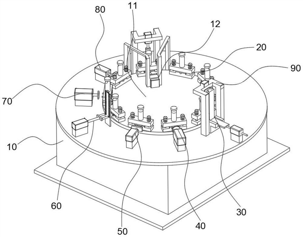
[0049] See Figure 1 ~ 11 In the embodiment of the present invention, a U-shaped tube processing apparatus includes a base 10, and a carrier assembly 11 is provided on the base 10. The carrier assembly 11 includes a rotating motor disposed inside the base 10, and the output shaft of the rotating motor is vertically extending out of the working table surface of the base 10, and the rotating electric machine is connected to the shaft 111. A clamp assembly 20 is uniformly distribute...


PUM


Abstract

The invention relates to the technical field of mechanical equipment manufacturing, in particular to a U-shaped pipe machining device which comprises a carrying assembly, a clamping assembly is arranged on the carrying assembly, and the carrying assembly carries the clamping assembly to sequentially enter a U-shaped pipe feeding assembly, a first alignment assembly, a shaping assembly, a circular ring feeding assembly, a second alignment assembly and a circular ring positioning assembly which are arranged on a base. The U-shaped pipe feeding assembly pushes a U-shaped pipe into the clamping cavity, the first alignment assembly abuts against two pipe openings, the shaping assembly conducts corresponding circle expanding action on the deformed pipe openings of the aligned U-shaped pipe, the circular ring feeding assembly abuts against the outer circumferences of the two pipe openings in a sleeving mode, the second alignment assembly abuts against the pipe openings of the U-shaped pipe subjected to ring sleeving, and the shaping assembly conducts shaping action on the deformed pipe openings of the U-shaped pipe subjected to ring sleeving. The circular ring positioning assembly pushes circular rings on the pipe opening to the outlet of the clamping cavity along the axis of the pipe opening so that the two circular rings can be symmetrically distributed on the U-shaped pipe. The circular ring can be stably and firmly connected to the U-shaped pipe in a sleeving mode, meanwhile, the U-shaped pipe is not prone to deformation and damage, and the one-time passing rate of finished products is increased.

Description

Technical field [0001] The present invention relates to the field of mechanical equipment manufacturing techniques, and is specifically a U-tube processing apparatus. Background technique [0002] In the heat exchanger in the refrigeration device, the U-tube and the jacket connected thereto are very cumbersome, which is usually done by the workers or by different processing machines, and the working efficiency is low. In order to effectively increase the connection of the U-tube and the collar, the set routine is also produced on the market. The existing collar machine consists of a working platform, a rotating disk, a fixture of a rotating disk, and several machining stations. Existing working top platforms are in fixed U-tank: one, the U-tube is usually fixed, and in subsequent work, due to the displacement of the U-tube, it will cause the opposite to complete the corresponding Process step; Second, the ring socket is not easily dropped in the process of the upper ring; the thi...

Claims


Application Information

Patent Timeline
Patent Type & Authority Applications(China)
IPC IPC(8): B23P19/00B23P19/02
CPCB23P19/001B23P19/02
Inventor 金家喜殷涛卫功成
Owner HEFEI JINLIFENG MACHINERY
Features
  • R&D
  • Intellectual Property
  • Life Sciences
  • Materials
  • Tech Scout
  • Unparalleled Data Quality
  • Higher Quality Content
  • 60% Fewer Hallucinations
Learn More