
Auxiliary braking device for brake

A technology of auxiliary braking and brakes, which is applied in the field of vehicles, can solve problems such as failure to brake, vehicle slipping out of control, braking stroke, and brake failure, etc., and achieve the effects of shortening the braking stroke, simple and ingenious overall structure design, and good versatility

Inactive Publication Date: 2022-03-08
原长青
View PDF0 Cites 0 Cited by
  • Summary
  • Abstract
  • Description
  • Claims
  • Application Information

AI Technical Summary

Problems solved by technology

[0003] The purpose of the present invention is to overcome the shortcomings of the prior art, and propose a kind of brake auxiliary braking device to solve the problem that the vehicle cannot brake when the brake fails, and solve the problem of vehicle slipping out of control and braking on steep slopes, ice and snow roads, and muddy roads. The problem of long travel, improve the safety factor of the vehicle

Method used


Image

  • Auxiliary braking device for brake
  • Auxiliary braking device for brake
  • Auxiliary braking device for brake

Examples


Embodiment 1

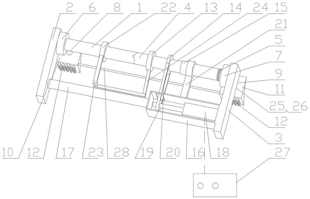
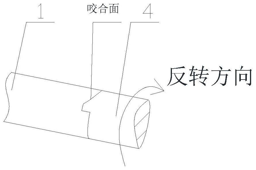
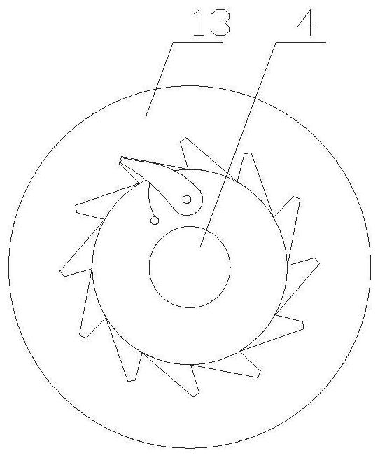
[0013]The main structure of the brake auxiliary braking device involved in this embodiment includes: a main shaft 1, a first longitudinal support rod 2, a second longitudinal support rod 3, a sliding shaft 4, a spring 5, a first iron chain box 6, a second iron chain Chain box 7, first iron chain 8, second iron chain 9, first brake 10, second brake 11, fixing nail 12, reverse pulley 13, second gear 14, small screw 15, motor box 16, lateral support Rod 17, motor 18, first gear 19, endless chain 20, second positioning rod 21, forward pulley 22, first positioning rod 23, third iron chain 24, leaf spring 25, first button 26, controller 27 and the long shaft 28; the two ends of the main shaft 1 are fixed on the first longitudinal support bar 2 and the second longitudinal support bar 3 on both sides through bearings and bearing seats, the right side of the main shaft 1 is covered with a sliding shaft 4, and the left side of the main shaft 1 The outer diameter of the side part is the ...

Embodiment 2

[0017] The main structure of the brake auxiliary braking device involved in this embodiment is the same as that of Embodiment 1. The first gear 19 is connected with the rotating shaft of the motor 18 through a sliding key. When the sliding shaft moves to the right or left, the The second gear 14 drives the first gear 19 to move to the right or to the left, reducing rotation or movement resistance.


PUM


Abstract

The invention belongs to the technical field of vehicle braking, and relates to an auxiliary braking device for a brake. The main body structure of the device comprises a main shaft, a first longitudinal supporting rod, a second longitudinal supporting rod, a sliding shaft, a spring, a first iron chain box, a second iron chain box, a first iron chain, a second iron chain, a first brake, a second brake, a fixing nail, a reverse pulley, a second gear, a small spiral, a motor box, a transverse supporting rod, a motor, a first gear, an annular chain, a second positioning rod and a forward pulley. The device comprises a main shaft, a first positioning rod, a third iron chain, a spring piece, a first button, a controller and a long shaft, the right side of the main shaft is sleeved with a sliding shaft, a spring is arranged at the right end of the sliding shaft, a reverse pulley, a second gear and a small spiral are sequentially arranged on the sliding shaft from left to right, and the reverse pulley is of an inner ratchet wheel structure; secondary emergency braking is achieved when a vehicle brake fails, the auxiliary brake achieves braking, the braking stroke is shortened, and the device is simple and ingenious in overall structural design, safe, reliable, convenient to operate and popularize and environmentally friendly in application.

Description

Technical field: [0001] The invention belongs to the technical field of vehicle braking, and relates to a brake auxiliary braking device, in particular to a self-rescue braking device capable of emergency braking when the vehicle brake fails, and can also be used to drive the vehicle on steep slopes, ice and snow roads, and muddy roads. In the case of loss of control, it plays the role of braking or auxiliary brake braking. Especially suitable for cars, trucks, tricycles and other vehicles. Background technique: [0002] In the era of efficiency and time, automobiles and other means of transportation can bring great benefits to the convenience of human transportation, reduce unnecessary time on the road, and bring comfort to travel no matter in hot sun or rainy and snowy weather. With the improvement of people's living standards, cars and other means of transportation have gradually entered people's lives and families. Individual driving travel can shorten the traffic time ...

Claims


Application Information

Patent Timeline
Patent Type & Authority Applications(China)
IPC IPC(8): B60T1/14
CPCB60T1/14B60T2201/03
Inventor 原长青郝会娟
Owner 原长青
Learn More