Novel homopolar inductor motor for flywheel energy storage

A flywheel energy storage and inductor technology, applied in electrical components, electromechanical devices, electric components, etc., can solve problems such as the difficulty of dissipating the heat of the stator, reducing the operating efficiency of the motor, and the large excitation copper loss of the motor, so as to eliminate the space harmonics. Magnetic field, improve operating efficiency, eliminate the effect of excitation copper loss

Pending Publication Date: 2022-03-08
威海奥文工业科技有限公司 +1
View PDF6 Cites 0 Cited by
  • Summary
  • Abstract
  • Description
  • Claims
  • Application Information

AI Technical Summary

Problems solved by technology

According to different excitation methods, the induction motor can be divided into permanent magnet induction motor or electric excitation induction motor. In the flywheel energy storage system, the induction motor usually adopts the form of electric excitation, so as to adjust the magnitude of the excitation current. The air gap magnetic field, however, due to the existence of the excitation winding, when the same-polarity induction motor is charging and discharging, the excitation current needs to be passed through the excitation winding to generate the excitation magnetic field, resulting in a large excitation copper loss for the motor. And it causes the excitation winding to heat up, and the heat of the stator is not easy to dissipate under vacuum conditions, thereby reducing the operating efficiency of the motor. Therefore, permanent magnet excitation can be used to replace electric excitation, and permanent magnet rings can be used to replace the excitation winding
However, due to the excitation of permanent magnets, it will bring a certain no-load loss, resulting in a certain self-dissipation rate of the motor. For large-scale energy storage flywheels, it is necessary to study motors that reduce motor losses and have better performance.

Method used


Image

  • Novel homopolar inductor motor for flywheel energy storage
  • Novel homopolar inductor motor for flywheel energy storage
  • Novel homopolar inductor motor for flywheel energy storage

Examples


Embodiment Construction

[0022] The following will clearly and completely describe the technical solutions in the embodiments of the present invention with reference to the drawings in the embodiments of the present invention. Based on the embodiments of the present invention, all other embodiments obtained by persons of ordinary skill in the art without making creative efforts belong to the protection scope of the present invention.

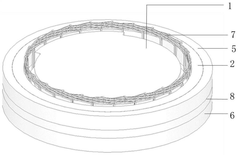
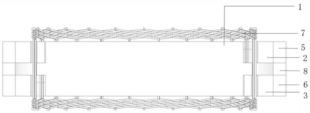
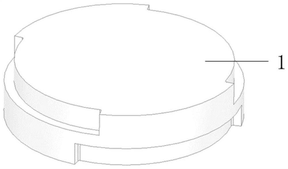
[0023] see Figure 1-7 , an embodiment provided by the present invention: a new homopolar induction motor for flywheel energy storage, including a rotor 1, an upper stator core 2, a lower stator core 3, an upper magnetic ring 5, a lower magnetic ring 6, The stator winding 7 and the permanent magnet ring 8, the outer side of the rotor 1 is provided with a stator, the stator includes an upper stator core 2, a lower stator core 3, an upper magnetic ring 5, a lower magnetic ring 6, a stator winding 7 and a permanent magnet ring 8;

[0024] The rotor 1 is a solid structure,...


PUM


Abstract

The invention discloses a novel homopolar inductor motor for flywheel energy storage, which comprises a rotor, an upper stator iron core, a lower stator iron core, an upper magnetic conductive ring, a lower magnetic conductive ring, a stator winding and a permanent magnet ring, and is characterized in that a stator is arranged on the outer side of the rotor and comprises an upper stator iron core, a lower stator iron core, an upper magnetic conductive ring, a lower magnetic conductive ring, a stator winding and a permanent magnet ring. A new motor working principle and a new motor structure are adopted, the motor has radial magnetic flux and axial magnetic flux, a permanent magnet excitation mode is adopted, and compared with an electric excitation like-pole inductor motor, excitation copper loss during charging/discharging operation can be eliminated, temperature rise of a stator winding is reduced, heat dissipation pressure is relieved, and therefore the operation efficiency of the motor is improved; the upper stator iron core and the lower stator iron core adopt a gullet-free structure, and a space harmonic magnetic field generated by iron core slotting is eliminated, so that the eddy current loss of the rotor can be greatly reduced.

Description

technical field [0001] The invention relates to the technical field of motors, in particular to a novel homopolar induction sub-motor for flywheel energy storage. Background technique [0002] The high-speed motor in the flywheel energy storage system is the most important part of energy conversion, so the performance of the flywheel motor has a great influence on the performance of the entire flywheel energy storage system. The flywheel motor must meet the requirements of the flywheel energy storage system, such as high speed, high efficiency, high reliability, etc. At present, the motors used in the flywheel energy storage system include asynchronous motors, synchronous motors, switched reluctance motors, induction motors and other structures of motors. Among them, the induction sub-motor has a series of advantages such as its simple rotor structure, suitable for high-speed operation, and small no-load loss, and has a wide range of application prospects. [0003] The str...

Claims


Application Information

Patent Timeline
Patent Type & Authority Applications(China)
IPC IPC(8): H02K7/02H02K1/12H02K1/18H02K1/24H02K3/04H02K16/04
CPCH02K7/025H02K1/12H02K1/185H02K1/24H02K3/04H02K16/04H02K2213/03H02K2201/03Y02E60/16
Inventor 于飞冯开杰徐衍亮于大勇王月川卢楠顾强张俊杰于双嘉卞敬业
Owner 威海奥文工业科技有限公司
Why Eureka
Try Eureka