
Common-mode active filter with simplified structure

A source filter and common-mode technology, which is applied in the field of common-mode active filters and their implementation circuits, can solve the problems of active filter optimization difficulties, many requirements, and single implementation methods

Pending Publication Date: 2022-03-08
XI AN JIAOTONG UNIV
View PDF0 Cites 0 Cited by
  • Summary
  • Abstract
  • Description
  • Claims
  • Application Information

AI Technical Summary

Problems solved by technology

[0005] However, the current implementation of active filters is relatively simple, and there are more requirements for the number of components, which will make further optimization of active filters difficult

Method used


Image

  • Common-mode active filter with simplified structure
  • Common-mode active filter with simplified structure
  • Common-mode active filter with simplified structure

Examples


Embodiment 1

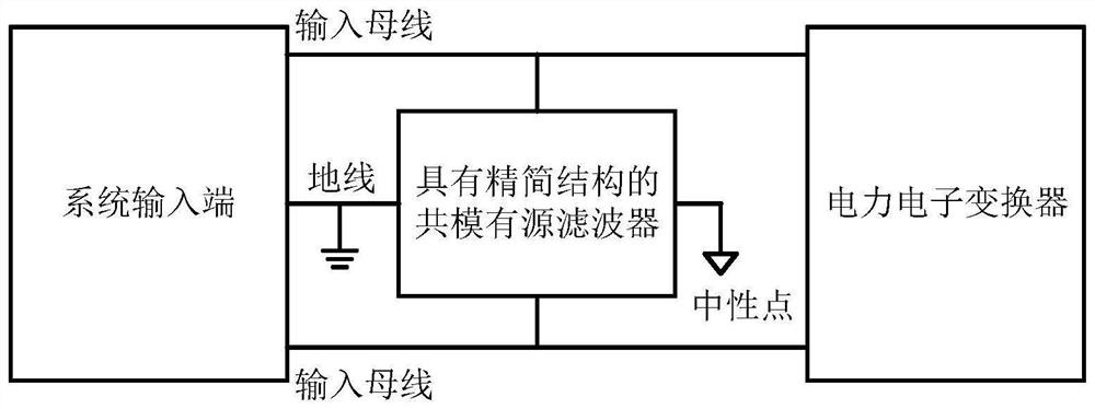
[0014] Please refer to figure 1 , figure 1 It is a schematic connection diagram of the application of the common-mode active filter circuit with a simplified structure proposed by the present invention. An embodiment of the present invention provides a common-mode active filter circuit with a simplified structure, the common-mode active filter with a simplified structure is connected to the busbar at the input end, and is connected in parallel with the power electronic converter of the subsequent stage . In addition, the common-mode active filter with a simplified structure is connected to the ground of the input end of the circuit system, and has an additional neutral point.

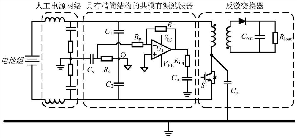
[0015] Please refer to figure 2 , shown in the figure includes a battery pack, an artificial power network, a common-mode active filter with a simplified structure and a power electronic converter, and a schematic diagram of a common-mode active filter with a simplified structure proposed by the pre...


PUM


Abstract

The invention discloses a common-mode active filter with a simplified structure. A circuit of the common-mode active filter is mainly composed of a neutral point construction circuit, a noise signal sampling circuit, a noise signal amplification circuit and a noise signal compensation circuit. A neutral point generated by the neutral point construction circuit serves as a reference point of the common-mode active filter circuit with the simplified structure. A common-mode interference signal is sampled by the noise signal sampling circuit and then amplified by the noise signal amplification circuit, and finally a corresponding compensation signal is generated on the noise signal compensation circuit. The generated compensation signal and a common-mode interference signal in the circuit can be counteracted with each other, so that the purpose of noise suppression is achieved. According to the invention, effective suppression of a common-mode interference signal can be realized through a small number of components and a small circuit volume, so that the miniaturization design of the active filter is realized.

Description

technical field [0001] The invention relates to the field of electromagnetic compatibility, in particular to a common-mode active filter with a simplified structure and a realization circuit thereof. Background technique [0002] Small size, high switching frequency, high power and high power density have always been the goals pursued by the development of power electronics technology. With the emergence and application of a new generation of semiconductor devices, such as silicon carbide devices and gallium nitride devices, the switching frequency of power electronic devices has been significantly increased, which reduces the size of power electronic devices and greatly increases the power density. However, higher switching frequency and smaller size will make the electromagnetic interference problem more prominent. In the transient state of high-speed switching of switching devices, extremely fast voltage and current mutations will occur. This high-speed voltage and curre...

Claims


Application Information

Patent Timeline
IPC IPC(8): H02M1/44
CPCH02M1/44Y02E40/40
Inventor 周永兴陈文洁陈钰宣孟鑫任鹏远黄兴伟
Owner XI AN JIAOTONG UNIV
Learn More