Steel structure butt joint positioning device for building construction

A positioning device and construction technology, applied in the direction of building structure, construction, covering/lining, etc., can solve problems such as looseness, achieve the effect of convenient loading and unloading, ensure firmness, and avoid loosening

Inactive Publication Date: 2022-03-11
程诗栋
View PDF1 Cites 0 Cited by
  • Summary
  • Abstract
  • Description
  • Claims
  • Application Information

AI Technical Summary

Problems solved by technology

[0004] Although the overall device has achieved the docking and fixing work of the steel structure columns, the connection of the overall structure is mostly fixed by traditional bolts and nuts, and it will loosen if left in the external environment for a long time. Therefore, there is an urgent need for a steel structure for construction. Structural docking positioning device

Method used


Image

  • Steel structure butt joint positioning device for building construction
  • Steel structure butt joint positioning device for building construction
  • Steel structure butt joint positioning device for building construction

Examples


Embodiment 1

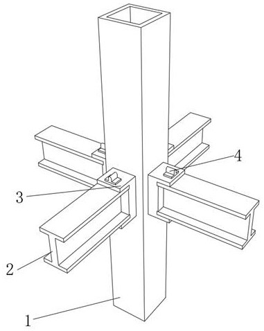
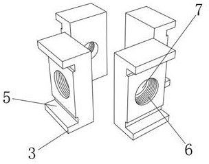
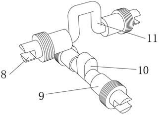
[0033] A steel structure docking positioning device for building construction, such as Figure 1-4 As shown, it includes a rectangular steel plate 1, and the outer walls around the middle section of the rectangular steel plate 1 are respectively fixed with U-shaped positioning plates 3 by a stabilizing mechanism, and the top outer wall of each U-shaped positioning plate 3 is provided with a plug-in slot. The inner wall of the connection groove is provided with a snap-in mechanism 4, and one side of each U-shaped positioning plate 3 is provided with two snap-in slots 5, and each two snap-in slots 5 are respectively fixed with the same H-shaped snap-in mechanism 4. Connecting steel 2; when in use, pre-install the stabilizing mechanism around the inner middle section of the rectangular steel plate 1, and install four U-shaped positioning plates 3 around the rectangular steel plate 1, and then insert each U through the clamping mechanism 4 In the insertion slot of the U-shaped pos...

Embodiment 2

[0039] A steel structure docking positioning device for building construction, such as Figure 5 As shown, in order to complete the docking and positioning of cylindrical steel plates; this embodiment makes the following improvements on the basis of embodiment 1: the outer walls of the opposite sides of the four H-shaped connecting steels 2 are respectively welded with arc-shaped welding plates 18 , and the tops and bottoms of the four arc-shaped welding plates 18 are respectively welded with two mounting plates 16, and the two mounting plates 16 are fixed with equidistantly distributed pin columns 17 by threads on the outer walls of the circumference of the two mounting plates 16, and each mounting plate 16 is close to The top and bottom of one side of each H-shaped connecting steel 2 are plugged with the same clamping strip 19, and the circumferential inner walls of the two mounting plates 16 are welded with the same circular steel plate 15; The setting of the column 17 and ...


PUM


Abstract

The invention discloses a steel structure butt joint positioning device for building construction, and relates to the technical field of steel structure butt joint positioning. The problem of steel structure butt joint quality is solved. The device specifically comprises a rectangular steel plate, U-shaped positioning plates are fixed to the outer walls of the periphery of the middle section of the rectangular steel plate through stabilizing mechanisms correspondingly, an inserting groove is formed in the outer wall of the top of each U-shaped positioning plate, a clamping mechanism is arranged on the inner wall of each inserting groove, and two clamping grooves are formed in one side of each U-shaped positioning plate; and the same H-shaped connecting steel is fixed in every two clamping grooves through a clamping mechanism, the stabilizing mechanism comprises four mounting holes, four limiting rings, four U-shaped clamping columns, four T-shaped mounting columns, a stabilizing convex plate and a U-shaped limiting block, and each mounting hole is formed in the center of one side of each U-shaped positioning plate. According to the method, the problem of hidden danger of loosening caused by butt joint and fixation through traditional bolts is avoided, and the butt joint and positioning efficiency of the rectangular steel plate and the H-shaped connecting steel is guaranteed.

Description

technical field [0001] The invention relates to the technical field of steel structure docking positioning, in particular to a steel structure docking positioning device for building construction. Background technique [0002] Steel structures are widely used in construction. Multi-high-rise medium steel structure columns are divided into multiple hoisting units according to the site conditions and then spliced ​​on site. At present, the main assembly and positioning methods of steel structure columns use upper and lower ear plates to pull screw connections and upper and lower ear plates. There are two kinds of double splint bolt connection. [0003] After retrieval, the Chinese patent application number is CN202020704098.X, which discloses a butt joint positioning device for steel structure columns, including a positioning head and a positioning sleeve, the positioning head cooperates with the positioning sleeve, and the lower end of the positioning head is provided with a ...

Claims


Application Information

Patent Timeline
Patent Type & Authority Applications(China)
IPC IPC(8): E04B1/24E04B1/58
CPCE04B1/24E04B1/2403E04F13/0803E04B2001/2406E04B2001/2415E04B2001/2418E04B2001/2421
Inventor 程诗栋
Owner 程诗栋
Why Eureka
Try Eureka