Strip type working face filling mining method

A mining method and working face technology, which is applied in the direction of filling, ground mining, mining equipment, etc., can solve the problems of gas accumulation, high operation requirements, and insufficient air volume, and achieve the prevention of gas and heat accumulation, high safety, and simple operation Effect

Active Publication Date: 2022-03-11
中煤科工能源科技发展有限公司
View PDF3 Cites 0 Cited by
  • Summary
  • Abstract
  • Description
  • Claims
  • Application Information

AI Technical Summary

Problems solved by technology

When the strip parallel ventilation method is used to mine the strip filling mining face, the unfilled strip will disperse the fresh air volume entering from the groove to each strip, so that the air volume in each strip is insufficient, and the air volume in the strip is insufficient. The scattered leftover coal is not completely oxidized, and the heat accumulates, which is easy to cause spontaneous combustion and pose a safety hazard
At the same time, the parallel ventilation of the unfilled strips has been penetrated, and the length of the ventilation routes is different, forming a relatively complex ventilation network. The air distribution volume of each strip needs to be strictly calculated, and the ventilation adjustment device is required to accurately control the air, which is difficult to adjust and difficult to adapt to the conditions. The dynamic change of the continuous formation and continuous filling of the belt
However, when the closed strip ventilation channel is used to mine the strip working face, the coal wall in the unfilled strip is exposed, and the gas gradually escapes into the air in the strip, resulting in gas accumulation or exceeding the limit.
When unsealing before filling, it is necessary to take special measures to exhaust the accumulated gas. The operation is difficult, the operation requirements are high, and there are potential safety hazards, which will affect the normal operation of the nearby mining filling system.

Method used


Image

  • Strip type working face filling mining method
  • Strip type working face filling mining method
  • Strip type working face filling mining method

Examples


Embodiment Construction

[0043] Embodiments of the invention are described in detail below, examples of which are illustrated in the accompanying drawings. The embodiments described below by referring to the figures are exemplary and are intended to explain the present invention and should not be construed as limiting the present invention.

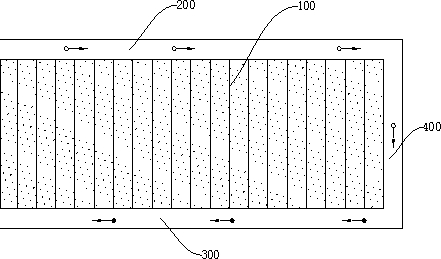
[0044] Refer below Figure 1 to Figure 6 The zigzag ventilated strip working face filling mining method according to the embodiment of the present invention is described.

[0045] The strip-type working face filling and mining method with zigzag ventilation according to the embodiment of the present invention comprises the following steps:

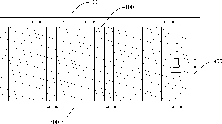
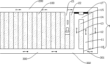
[0046] 1) Digging in and out of the transportation chute 200, the return air chute 300 and the cutout 400 to form the working face 100 to be mined and a U-shaped ventilation channel. The working face 100 to be mined includes N mining areas, and N is an integer greater than or equal to 2 ;

[0047] 2) Excavate the first min...


PUM


Abstract

The embodiment of the invention provides a broken-line-shaped ventilation strip type working face filling mining method which comprises the following steps that (1) a transportation crossheading, an air return crossheading and an open-off cut are excavated to form a working face to be mined and a U-shaped ventilation channel, the working face to be mined comprises N mining areas, and N is an integer larger than or equal to 2; 2) tunneling the first mining area according to a strip type coal mining method and forming a first unfilled strip, a first coal pillar, a second unfilled strip, a second coal pillar and a first communication channel; (3) the conveying gate road, the cut hole, one part of the air return gate road, the first unfilled strip, the first communication channel, the second unfilled strip and the other part of the air return gate road are sequentially connected so as to form a ventilation channel; and 4) repeating the step 2) to the step 3) to form a new ventilation channel.Therefore, the strip type working face filling mining method has the advantages of high safety, simple and convenient equipment and convenience in operation.

Description

technical field [0001] The invention relates to the technical field of coal mining, in particular to a strip-type working face filling and mining method with zigzag ventilation. Background technique [0002] The strip filling mining of the longwall working face can prevent surface subsidence and prevent the movement of rock formations caused by mining from damaging the protected objects such as water bodies and buildings on the surface. Ventilation passages in longwall working face strip filling mining play an important role in mining safety and reliability. [0003] In related technologies, the air ducts formed during the strip filling mining of the longwall working face mainly include strip parallel ventilation channels and closed strip ventilation channels. When the strip parallel ventilation method is used to mine the strip filling mining face, the unfilled strip will disperse the fresh air volume entering from the groove to each strip, so that the air volume in each st...

Claims


Application Information

Patent Timeline
Patent Type & Authority Applications(China)
IPC IPC(8): E21C41/18E21F15/06
CPCE21C41/18E21F15/06
Inventor 刘宁宁李磊姚再兴樊强利杨洋曹牧池津维刘堉杉曹克楠高升张力元
Owner 中煤科工能源科技发展有限公司
Why Eureka
Try Eureka