Refrigerator

A refrigerator and air inlet duct technology, applied in the field of refrigeration equipment, can solve the problems of limited defrosting effect, complex air duct structure, aggravated frosting, etc., and achieve the effects of large space utilization rate, improved energy saving efficiency, and reduced energy consumption

Pending Publication Date: 2022-03-11
GREE ELECTRIC APPLIANCES INC
View PDF0 Cites 0 Cited by
  • Summary
  • Abstract
  • Description
  • Claims
  • Application Information

AI Technical Summary

Problems solved by technology

[0003] In view of this, the present invention provides a refrigerator to solve the problems in the prior art that the water vapor in the mechanical room enters the evaporator room and aggravates the frosting, the defrosting effect is limited, and the air duct structure is complicated.

Method used


Image

  • Refrigerator
  • Refrigerator
  • Refrigerator

Examples


Embodiment 1

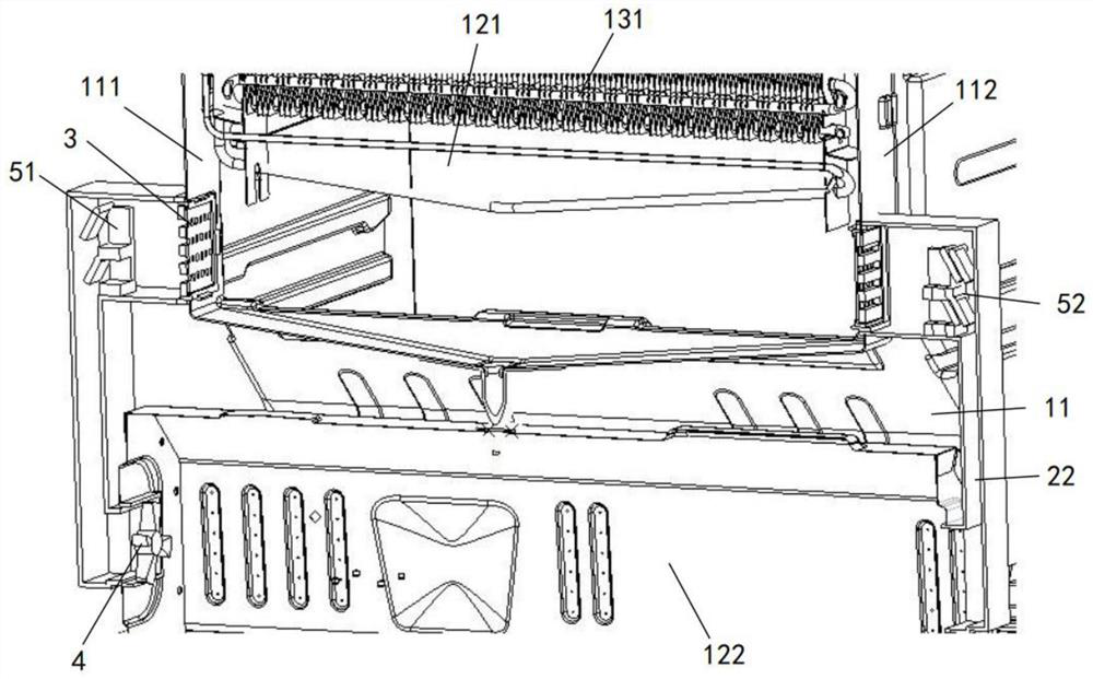
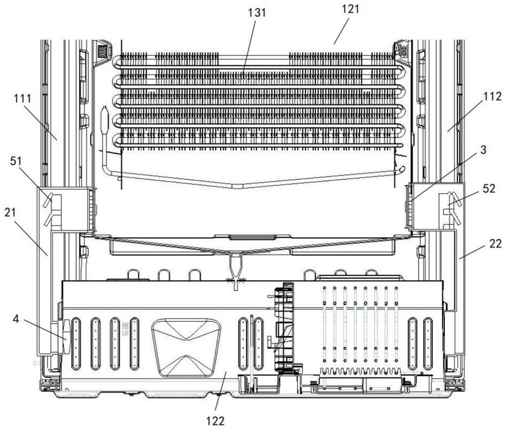
[0054] Such as Figure 1a and Figure 1b As shown, this embodiment provides a refrigerator, and the refrigerator includes a first compartment 121, a second compartment 122 arranged along the height direction of the refrigerator, and an air inlet duct 21 and a return duct connecting the first compartment 121 and the second compartment 122. Air duct 22; the first chamber 121 accommodates the evaporator 131, the second chamber 122 accommodates the compressor, and the air inlet duct 21 and the return air duct 22 are relatively arranged between the first compartment 121 and the second compartment 122 ; The air inlet channel 21 is used to send the hot and humid air in the second room 122 into the first room 121; the air return channel 22 is used to send the defrosted air in the first room 121 into the second room 122; the air inlet duct 21 and the air return duct 22 are provided with control dampers;

[0055] At least one of the air inlet channel 21 and the air return channel 22 is...

Embodiment 2

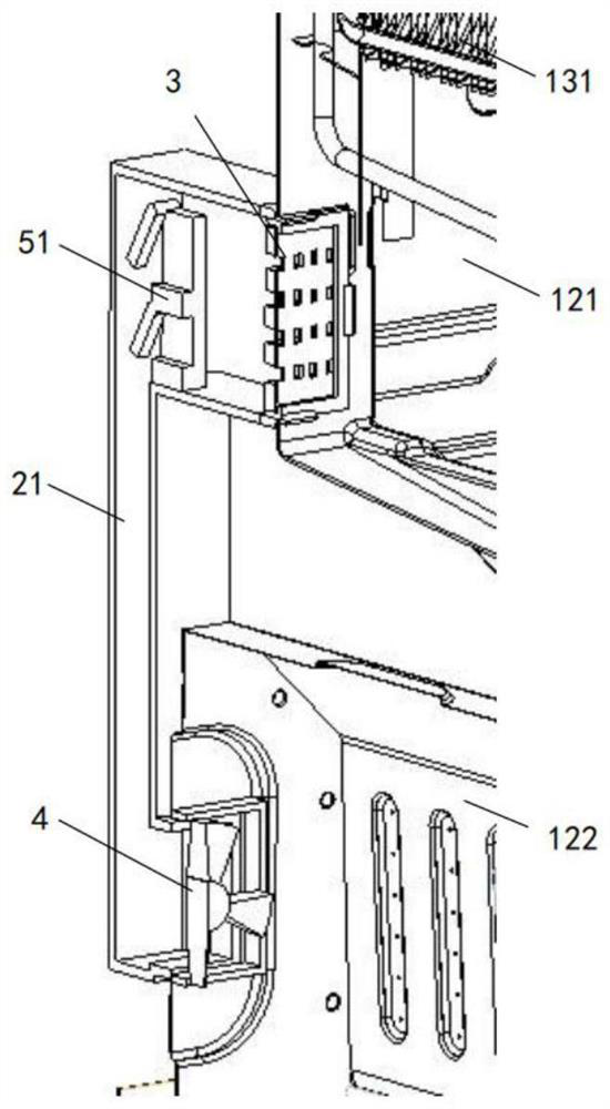
[0077] The difference from Embodiment 1 is that the dehumidification assembly 3 includes a plurality of baffles arranged at intervals along the first air inlet or the first air outlet; the plurality of baffles form an angle α with the flow direction of the air, where 0° <α<90°; a water receiving tank is provided under the multiple baffles; a second flow channel is formed between adjacent baffles;

[0078] When the refrigerator is in the defrosting mode, when the hot and humid air flows through the second flow channel, the water vapor in it collides with the baffle and coalesces into water droplets, and then drops into the water receiving tank along the baffle, so that the hot and humid air is transformed into The hot air is dried, and then the evaporator 131 is defrosted to improve the defrosting effect.


PUM


Abstract

The invention provides a refrigerator. The refrigerator comprises a first chamber, a second chamber, an air inlet duct and an air return duct. An evaporator is contained in the first chamber, a compressor is contained in the second chamber, and the air inlet duct and the air return duct communicate with the first chamber and the second chamber; a dehumidification assembly is arranged in at least one of the air inlet duct and the air return duct; when the refrigerator is in a defrosting mode, humid and hot air in the second chamber enters the first chamber through the air inlet duct, the humid and hot air is converted into dry and hot air when flowing through the dehumidification assembly, then the evaporator is defrosted, and the defrosted air returns to the second chamber through the air return duct; hot air is dried, the defrosting effect is improved, the problem that water vapor in hot air aggravates frosting of the evaporator is avoided, heat in the second chamber is fully utilized, the evaporator is defrosted, extra electric energy does not need to be consumed, the energy utilization rate of the refrigerator is improved, pressure balance in the first chamber is guaranteed, and the service life of the refrigerator is prolonged. And the temperature of the first chamber can be maintained in the defrosting process of the refrigerator.

Description

technical field [0001] The invention relates to the technical field of refrigeration equipment, in particular to a refrigerator. Background technique [0002] The application of refrigerators meets the needs of users for prolonging the freshness of food, but the water vapor in the air in the refrigerator is in a low-temperature environment, and it is easy to condense into frost on the surface of the evaporator, thereby affecting the normal operation of the evaporator; the existing technology mainly Use electric heating wire to heat the evaporator to defrost, but this method consumes a lot of power, the heating coverage is narrow, and the defrosting effect is poor; at the same time, the waste heat discharged from the compressor and condenser in the mechanical room is not used, resulting in resources. Waste; some people propose to connect the air induction component between the mechanical room and the evaporation room. In the defrosting mode, the hot air generated by the compr...

Claims


Application Information

Patent Timeline
Patent Type & Authority Applications(China)
IPC IPC(8): F25D11/00F25D17/04F25D17/06F25D17/08F25D21/12F25D29/00
CPCF25D11/00F25D17/042F25D17/062F25D17/08F25D21/125F25D21/004F25D29/003F25D29/005F25D2317/04111F25D2317/067
Inventor 刘继宗
Owner GREE ELECTRIC APPLIANCES INC
Why Eureka
Try Eureka