Check patentability & draft patents in minutes with Patsnap Eureka AI!

Pluggable electrode and insulating oil discharge test device

A technology of discharge test and insulating oil, applied in the direction of measuring device, measuring device casing, measuring electricity, etc., can solve the problems of consumption, multi-metal material and processing time, inconvenient replacement and installation process, etc., to reduce manufacturing cost and save production. Material, the effect of speeding up the replacement

Pending Publication Date: 2022-03-11
GUANGZHOU POWER SUPPLY BUREAU GUANGDONG POWER GRID CO LTD
View PDF0 Cites 0 Cited by
  • Summary
  • Abstract
  • Description
  • Claims
  • Application Information

AI Technical Summary

Problems solved by technology

In the experiment, it is often necessary to change the radius of curvature of the needle electrode to simulate different electric field uniformity. In the past, the entire needle electrode needs to be replaced. Not only is the replacement and installation process inconvenient, but also it is necessary to make a variety of needle electrodes to meet the demand, resulting in more metal consumption. Material and processing time

Method used


Image

  • Pluggable electrode and insulating oil discharge test device
  • Pluggable electrode and insulating oil discharge test device
  • Pluggable electrode and insulating oil discharge test device

Examples


Embodiment 1

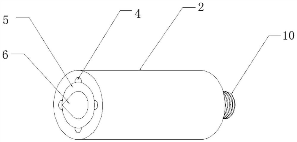
[0027] Such as figure 1 The schematic diagram of the structure of the pluggable electrode 1 shown, the electrode includes:

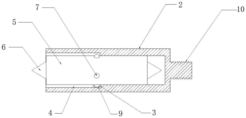
[0028] The electrode tube 2 has a plurality of limiting grooves 3 along the circumference, and a plurality of guide grooves 4 along the axial direction. One end of all the guide grooves 4 communicates with different limiting grooves 3, and the other end extends to the At the nozzle at one end of the electrode tube 2;

[0029] The electrode rod 5 is provided with an electrode head 6 at the end, and a plurality of positioning beads 7 are provided on the side wall. During assembly, all the positioning beads 7 are respectively snapped into different limiting grooves 3 along the corresponding guide grooves 4 .

[0030] Specifically, the electrode tube 2 can be a conductive copper tube, and four limiting grooves 3 are evenly opened on the inner wall surface of the electrode tube 2. These four limiting grooves 3 surround the central axis of the electrode tube ...

Embodiment 2

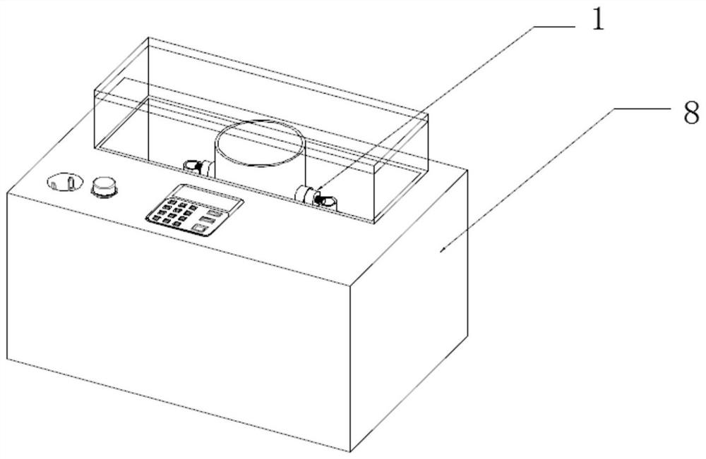
[0045]As shown in the schematic diagram of the structure of the insulating oil discharge test device, the test device includes a test box 8, and the test box 8 is equipped with a pluggable electrode 1, and the pluggable electrode 1 includes:

[0046] The electrode tube 2 has a plurality of limiting grooves 3 along the circumference, and a plurality of guide grooves 4 along the axial direction. One end of all the guide grooves 4 communicates with different limiting grooves 3, and the other end extends to the At the nozzle at one end of the electrode tube 2;

[0047] The electrode rod 5 is provided with an electrode head 6 at the end, and a plurality of positioning beads 7 are provided on the side wall. During assembly, all the positioning beads 7 are respectively snapped into different limiting grooves 3 along the corresponding guide grooves 4 .

[0048] Specifically, the electrode tube 2 can be a conductive copper tube, and four limiting grooves 3 are evenly opened on the inne...


PUM


Abstract

The invention discloses a pluggable electrode and an insulating oil discharge test device, the electrode comprises an electrode tube and an electrode rod, the inner wall surface of the electrode tube is provided with a limiting groove and a guide groove, one end of the guide groove is communicated with the limiting groove, and the other end of the guide groove extends to a tube opening of the electrode tube to form an L-shaped groove. An electrode tip is arranged at the end of the electrode stem, positioning beads are arranged on the side wall of the electrode stem, when the electrode is assembled, the positioning beads are inserted into the limiting grooves along the guide grooves, and then the electrode stem is rotated to enable the positioning beads to be clamped into the limiting grooves respectively. The insulating oil discharge test device comprises a test box and a pluggable electrode, and the pluggable electrode is assembled in an oil tank of the test box. When the electrode is replaced, the electrode rod can be pulled out from the electrode tube by reversely rotating the electrode rod and rotating the positioning ball into the guide groove, and then the replaced electrode rod is inserted into the electrode tube, so that the whole electrode does not need to be detached from the test box, and the replacement speed of the electrode in an insulating oil discharge test is increased; and the test efficiency is improved.

Description

technical field [0001] The invention relates to the technical field of testing dielectric strength or breakdown voltage, in particular to a pluggable electrode and an insulating oil discharge test device. Background technique [0002] In order to simulate the long-gap discharge of insulating oil under an uneven electric field, the actual test electrodes mostly use the "needle-plate" electrode system, and need to be used in conjunction with a specific long-gap test oil tank. In the experiment, it is often necessary to change the radius of curvature of the needle electrode to simulate different electric field uniformity. In the past, the entire needle electrode needs to be replaced. Not only is the replacement and installation process inconvenient, but also it is necessary to make a variety of needle electrodes to meet the demand, resulting in more metal consumption. materials and processing time. Contents of the invention [0003] Aiming at the deficiencies in the prior ar...

Claims


Application Information

Patent Timeline
IPC IPC(8): G01R31/12G01R1/04
CPCG01R31/1281G01R1/0408G01R1/0416
Inventor 黄青丹莫文雄宋浩永王勇王炜陈于晴李助亚赵崇智刘静吴培伟
Owner GUANGZHOU POWER SUPPLY BUREAU GUANGDONG POWER GRID CO LTD
Features
  • R&D
  • Intellectual Property
  • Life Sciences
  • Materials
  • Tech Scout
  • Unparalleled Data Quality
  • Higher Quality Content
  • 60% Fewer Hallucinations
Learn More