Method of improving outline of photoresist pattern

A technology of photoresist and photoresist layer, which is applied in the field of improving the profile of photoresist, and can solve problems such as top-view inspection results that are out of specification and unable to meet specifications

Inactive Publication Date: 2004-03-10
UNITED MICROELECTRONICS CORP
View PDF0 Cites 0 Cited by
  • Summary
  • Abstract
  • Description
  • Claims
  • Application Information

AI Technical Summary

Problems solved by technology

It can be seen from the figure that due to the phenomenon of positive defocus, the apex angle of the opening of the photoresist forms a so-called top reentrant angle (Top Reentrant), and the opening obtained by the scanning electron microscope is much smaller than the actual need, which cannot Conforms to specifications, must be reworked (Rework)
However, if you take its cross-sectional view, you can find that the size of the photoresist opening actually meets the specifications, but the result of the top view inspection is not up to specification due to the concave angle generated by the top angle of the opening.

Method used


Image

  • Method of improving outline of photoresist pattern
  • Method of improving outline of photoresist pattern
  • Method of improving outline of photoresist pattern

Examples


Embodiment Construction

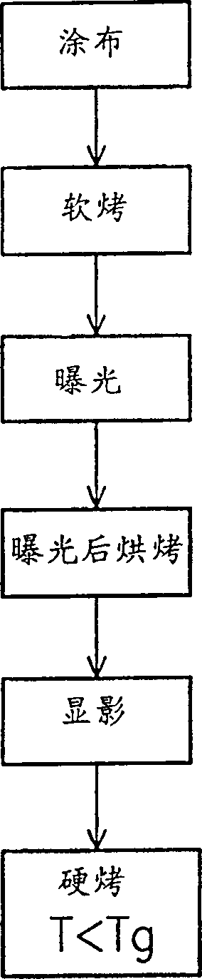
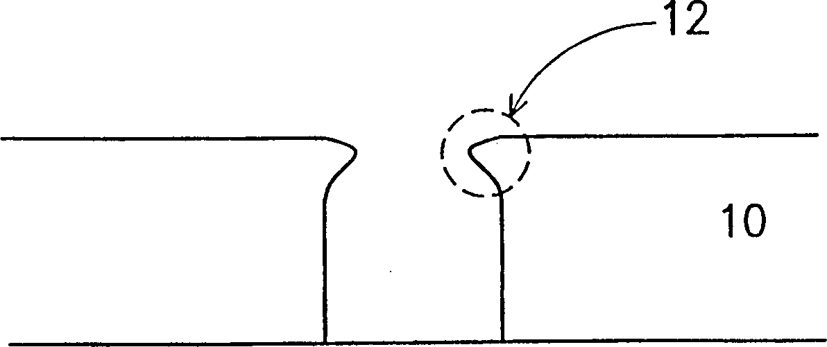
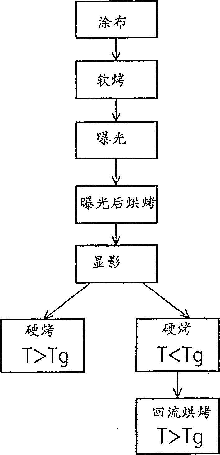
[0023] With the rapid development of semiconductor components and manufacturing processes, the size of the contact window has been reduced to 0.18 microns or smaller. Therefore, in order to improve the manufacturing process margin (Depthof Focus) higher than 0.6 microns in mass production ( Process) becomes quite difficult. In the general manufacture of contact windows, a photoresist layer is usually formed to define the pattern under the photoresist layer. For smaller contact windows, thermal reflow can be achieved by controlling the reflow temperature. A larger depth of focus is achieved, and a lower mask error factor (Mask Error Factor, MEF) is obtained to improve the profile of the photoresist. The present invention is a method of using thermal reflow to improve the defined profile of photoresists.

[0024] Please refer to figure 2 , which shows the flow of a method for improving the profile of a photoresist according to an embodiment of the present invention, and ima...


PUM


Abstract

The invented method is to proceed hard baking when temp. is under vitrescence transform temp. of the photic slushing agent after definiting exposure and develop steps of photic slushing agent, thus to make the photic slushing agent being been back-flow reshaped to avoid generation of point convex angle, reduce mask error factor and increased degree of uniformity of key size. The heard baking step can be substituted by two steps that to proceed back flow baking when temp. is below and super the vitrescence transform temp. of the photic slushing agent separately to achieve the same purpose.

Description

technical field [0001] The present invention relates to a method for improving the photoresist profile (Profile), and in particular to a method of using high temperature reflow (Hard Bake) to reflow the photoresist to improve its profile . Background technique [0002] The traditional method for defining a contact window or a via hole includes first forming a photoresist layer on the surface 100 where the contact window or via layer edge is to be formed, and then defining the photoresist layer to form an opening, exposing The portion of the lower layer where contact windows or via holes are to be formed. The traditional method of defining the photoresist layer, such as figure 1 As shown, including photoresist coating (Coating) 101, soft baking (SoftBake) 102, exposure (Exposure) 103, post-exposure baking (Post Exposure Bake) 104, development 105 and hard baking (Hard Bake) 106 and other steps. [0003] After exposure and development, the photoresist must go through a har...

Claims


Application Information

Patent Timeline
Patent Type & Authority Patents(China)
IPC IPC(8): G03F7/00G03F7/26H01L21/02H01L21/027H01L21/033
Inventor 黄义雄陈桂顺王见明
Owner UNITED MICROELECTRONICS CORP
Why Eureka
Try Eureka