
Large-truss-height adjustable suspended splicing combined type frame steel arch frame and large-span arch ring integral pouring process

An adjustable and combined technology, applied in arch bridges, buildings, bridge forms, etc., can solve the problems of steel arch segment transportation and construction, high construction cost, weak force and other problems, and achieves reduction of construction cost and construction period. The effect of saving and facilitating centralized management

Pending Publication Date: 2022-03-15
CHONGQING BIAOWANG MACHINERY EQUIP CO LTD
View PDF1 Cites 0 Cited by
  • Summary
  • Abstract
  • Description
  • Claims
  • Application Information

AI Technical Summary

Problems solved by technology

If it is necessary to apply the steel arch frame to the construction of the main arch ring with a large span (200-300 meters), there are three main technical routes: one is to stack multiple arch frames along the height direction to form an arch similar to the pancake type Structures (such as upper and lower two-story arches or upper, middle and lower three-story steel arches), adjacent arches are connected together. However, the biggest disadvantage of this pie-shaped arch structure is poor stability and many weak areas. Therefore, it has not been practically popularized and applied; the second is to thicken and heighten each section of the steel arch (such as the section of the steel arch with a span of 260 meters needs to be heightened to five meters or even higher). However, many roads have The height limit for driving and the construction of arch bridges are usually located in mountainous canyons or river valleys with rugged roads, which will inevitably bring huge difficulties to the transportation and construction of steel arch segments; Suspended cast section by section in the hanging basket, however, this process has very high requirements on the strength and rigidity of the anchor device and its infrastructure, especially the anchor device needs to bear the load of multiple cantilevered sections, it is used for large-span The construction of the main arch ring of the diameter also needs to be equipped with large-scale construction equipment. The construction process, especially the shifting process of the hanging basket, is very cumbersome and must be managed on both sides of the steel arch frame. There are problems such as high construction cost and long construction period.

Method used


Image

  • Large-truss-height adjustable suspended splicing combined type frame steel arch frame and large-span arch ring integral pouring process
  • Large-truss-height adjustable suspended splicing combined type frame steel arch frame and large-span arch ring integral pouring process
  • Large-truss-height adjustable suspended splicing combined type frame steel arch frame and large-span arch ring integral pouring process

Examples


Embodiment 1

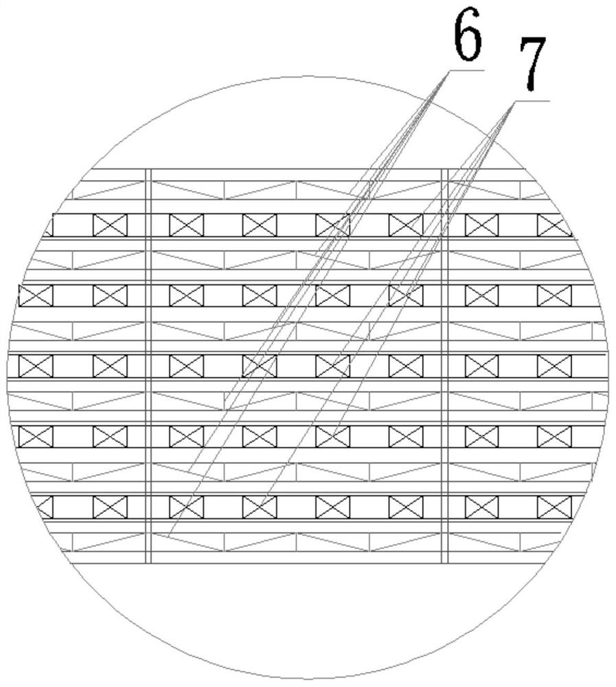
[0044] Such as Figure 1 to Figure 11 As shown, a large truss height-adjustable cantilever combined frame steel arch frame has a truss height of 5 meters and a span of 260 meters. The steel arch frame includes arch foot joints connected in sequence along the arc direction segment 100, a plurality of standard segments 200 (the segments between the arch foot segment 100 and the adjustment segment 300 all adopt the standard segment 200), the adjustment segment 300, the closing segment 400 and the closing device (the closing device adopts the current There is a closing device in the patent CN207862786U), multiple segments arranged side by side along the arch width direction form an arch rib, and the horizontal joints 4 and vertical joints 5 are used to connect adjacent arch ribs in the horizontal direction, and the upper and lower layers of truss and vertical Frames 3 are spliced ​​together to form an overall force-bearing arch frame, and the connection between the upper truss and...

Embodiment 2

[0061] A large truss height-adjustable cantilever combined frame steel arch frame, referring to Example 1 and combining Figure 14 to Figure 16 As shown, the main difference between it and Embodiment 1 is that two upper truss closed frame structural units 1 and two lower truss closed frame structural units 2 are arranged on each standard segment, and the standard segment The closed frame structure unit 1 of the upper truss can be snapped into the concave area 27 between adjacent trusses on the standard segment.

[0062] By adopting the scheme in the embodiment, it is only necessary to adopt the conventional span (within 150 meters) steel arch construction technology (including the facilities and equipment used in this process) to construct a 260m-span fabricated steel arch, which is suitable for large-scale facilities and equipment in mountainous areas The construction of the main arch ring of the large-span (200-300m) arch bridge in the valley / canyon that cannot be reached, a...


PUM


Abstract

The invention provides a large-truss-height adjustable suspended splicing combined type frame steel arch frame and an integrated large-span arch ring integral pouring process, the steel arch frame comprises an arch foot section, a standard section, an adjusting section, a closing section and a closing device which are sequentially connected in the arch arc line direction, and a plurality of sections arranged side by side in the arch width direction form an arch rib; the adjacent arch ribs are transversely connected through horizontal connecting pieces and vertical connecting pieces, the upper layer truss, the lower layer truss and the vertical frame are jointly spliced to form the overall stress type arch frame, and the connecting portion of the upper layer truss and the lower layer truss is located at the arc line of the middle of the arch. The process comprises the following steps: loading steel arch frame sections in a stacking manner, transporting the steel arch frame sections to a construction site, constructing arch foot sections, constructing standard sections, adjusting the sections, folding the sections, folding the steel arch frames, supporting an arch mold, and carrying out integral cast-in-place construction. The large-span steel arch has the advantages of being good in overall stability, uniform in stress, high in strength, adjustable in span, adjustable in arc, adjustable in breadth and the like, and the problems of transportation and construction of the large-span steel arch are solved.

Description

technical field [0001] The invention belongs to the technical field of construction of the main arch ring of an arch bridge, and in particular relates to an integral pouring process of a large truss height-adjustable suspension combined frame steel arch frame and an integrated large-span arch ring. Background technique [0002] The steel arch frame usually refers to the special support for construction measures used in the construction of the cast-in-place reinforced concrete main arch ring. system, longitudinal connection device) and standardized single structural parts, which are assembled at the construction site according to a certain combination method to form a special arch device that meets the project conditions, which is called a combined steel arch. Suspension assembly refers to the hoisting and installation process that transports the corresponding matching number of standardized single structural parts to the construction site and assembles them according to the ...

Claims


Application Information

Patent Timeline
Patent Type & Authority Applications(China)
IPC IPC(8): E01D21/10E01D4/00E01D19/00
CPCE01D21/10E01D4/00E01D19/00
Inventor 王华才王菲莹
Owner CHONGQING BIAOWANG MACHINERY EQUIP CO LTD
Learn More