A building wall structure

A technology for building walls and houses, which is applied to building components, building structures, buildings, etc., can solve the problems of reducing performance, wasting building materials, and easy loosening, and achieves improving performance, reducing limitations, and stabilizing good sex effect

Active Publication Date: 2022-05-31
金狮堂(江苏)建筑设计研究院有限公司
View PDF0 Cites 0 Cited by
  • Summary
  • Abstract
  • Description
  • Claims
  • Application Information

AI Technical Summary

Problems solved by technology

[0005] Aiming at the deficiencies of the prior art, the present invention provides a building wall structure, which solves the problem that the traditional building wall structure is integrated, cannot be disassembled and assembled, and can only be demolished and rebuilt, and cannot be reused, so it will be wasted A large amount of building materials is not conducive to saving and environmental protection. At the same time, it is impossible to adapt to some houses that need to be built quickly or temporarily. , prone to loosening, there is a greater potential safety hazard, reducing the problem of performance

Method used


Image

  • A building wall structure
  • A building wall structure
  • A building wall structure

Examples


Embodiment example 1

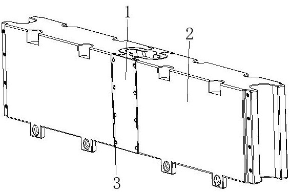
[0032] see Figure 1-6 , the present invention provides a technical solution: a building wall structure, comprising a connecting device 1, a wall panel device 2, and a fixing bolt 3, the wall panel device 2 is matched and connected to the two sides corresponding to the surface end of the connecting device 1, The fixing bolt 3 is screwed on the surface of the connecting device 1 at the position corresponding to the end of the surface of the wall panel device 2;

[0033] The connecting device 1 is provided with a base device 11, an elastic airbag 12, and a locking device 13. The surface end of the base device 11 is connected with the end of the wall panel device 2. The elastic airbag 12 is arranged on the inner wall of the base device 11. The locking device 13 is arranged inside the base device 11 and close to the position of the elastic airbag 12, the whole wall can be quickly spliced ​​into any size, easy to disassemble, save time and effort, strong adaptability, reduce limita...

Embodiment example 2

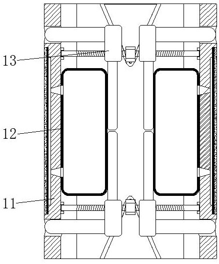
[0035] The connecting device 1 is provided with a base device 11, an elastic airbag 12, and a locking device 13. The surface end of the base device 11 is connected with the end of the wall panel device 2. The elastic airbag 12 is arranged on the inner wall of the base device 11. The locking device 13 is arranged inside the base device 11 and is close to the position of the elastic airbag 12;

[0036] The base device 11 is provided with a connecting base 111 , a fan-shaped gap 112 , an air cavity 113 , an elastic expansion layer 114 , and an anti-skid layer 115 . The elastic expansion layer 114 is arranged on the surface of the connection base 111 and at the position of the air cavity 113, and the anti-skid layer 115 is arranged on the surface of the elastic expansion layer 114. When the pressure plate 135 on the locking device 13 is in the connecting block When the 133 moves to both sides, pressure is applied to the elastic air bag 12. At this time, the compressed air inside t...

Embodiment example 3

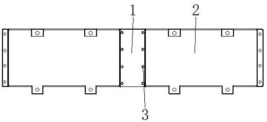
[0039] The wall panel device 2 is provided with a wall panel body 21 , a limit pin 22 , a pin groove 23 and an internal thread hole 24 , the limit pin 22 is arranged at the bottom of the wall panel body 21 and is located on the surface, and the pin groove 23 is opened in the wall panel body. On the top of the surface of 21 , the internal threaded hole 24 is opened inside the wall panel main body 21 and is located at the position of the limiting pin 22 and the pin groove 23 .

[0040] The limit pins 22 and the pin grooves 23 are located on the same line. The limit pins 22 are evenly distributed at the bottom of the wall panel body 21, and the pin grooves 23 are evenly distributed on the top surface of the wall panel body 21. The limit pins 22 and the pin grooves 23 are used. It is matched and fixed through the inner threaded hole 24, and then assembled with the connecting device 1 and the wall panel device 2, which can be continuously spliced, and then spliced ​​and disassembled...


PUM


Abstract

The invention discloses a building wall structure, which includes a connecting device, a wall board device, and fixing bolts. The ends are mated and connected, the elastic airbag is arranged on the inner wall of the base device, the locking device is arranged inside the base device and close to the elastic airbag, the air cavity is opened inside the connecting base and is located on the surface, and the elastic expansion layer is arranged on the connecting base The surface is located at the position of the air cavity, and the anti-skid layer is arranged on the surface of the elastic expansion layer. The invention relates to the technical field of building walls. The building wall structure of this house achieves the effect of fast splicing. The entire wall can be quickly spliced ​​into any size. It is convenient to disassemble and assemble, saves time and effort, has strong adaptability, reduces limitations, and at the same time reduces the impact of splicing gaps. The impact makes the installation firm, good stability, and improves the performance.

Description

technical field [0001] The invention relates to the technical field of building walls, in particular to a building wall structure. Background technique [0002] With the rapid growth of my country's national economy and the improvement of people's living standards, the overloaded development of my country's construction industry has brought a series of energy and environmental problems. At present, building energy consumption has become the soft underbelly of my country's economic development, and a huge number of high-energy-consumption buildings are lurking a huge energy crisis. Therefore, to achieve sustainable development of the construction industry, improvements in building materials are required to actively improve energy efficiency. Building walls are generally made of blocks or concrete cast-in-situ, while in rural areas most of them use block masonry. Therefore, blocks need to be stacked on top of each other during masonry, and then painted with concrete. Each bl...

Claims


Application Information

Patent Timeline
Patent Type & Authority Patents(China)
IPC IPC(8): E04B2/00E04C2/40
CPCE04B2/00E04C2/40Y02B10/10
Inventor 徐海琳
Owner 金狮堂(江苏)建筑设计研究院有限公司
Why Eureka
Try Eureka