Clamping tube light-load conduction control method and circuit in active clamping flyback topology

A technology of conduction control circuit and flyback topology, which is applied in the direction of control/regulation system, electrical components, and regulation of electrical variables, etc., which can solve the problems of Vds discharge, long conduction time, fixed conduction time, etc., and reduce the turn-on The effect of loss

Pending Publication Date: 2022-03-15
NANJING MICRO ONE ELECTRONICS
View PDF0 Cites 2 Cited by
  • Summary
  • Abstract
  • Description
  • Claims
  • Application Information

AI Technical Summary

Problems solved by technology

[0004] In the prior art, the clamp tube is only figure 2 The shown tc3 conducts for a short period of time, and the conduction time is often fixed. There are two possibilities: one is that the conduction time is too short, and the negative current generated in this case is not enough to discharge Vds. put in 0
see image 3 , at the time of te3, the clamp tube is only turned on for a short time, that is, the time of Ta0 is shorter than figure 2 In the ideal situation shown, Vds has not been fully discharged to 0 at this time, and the supervisor is turned on at the moment of te5. At this time, the Vds at the moment of conduction is not completely discharged to 0 potential; another situation is that the set conduction Pass time is too long, see Figure 4 As shown, if Ta0 is too long, Vds will drop quickly, and it will be discharged to 0 within the time of td4 and td5. In this case, the negative current generated is too large, which will cause potential instability of power transmission, etc. question

Method used


Image

  • Clamping tube light-load conduction control method and circuit in active clamping flyback topology
  • Clamping tube light-load conduction control method and circuit in active clamping flyback topology
  • Clamping tube light-load conduction control method and circuit in active clamping flyback topology

Examples


Embodiment Construction

[0032] In order to make the technical means, creative features, goals and effects achieved by the present invention easy to understand, the present invention will be further described below in conjunction with specific embodiments.

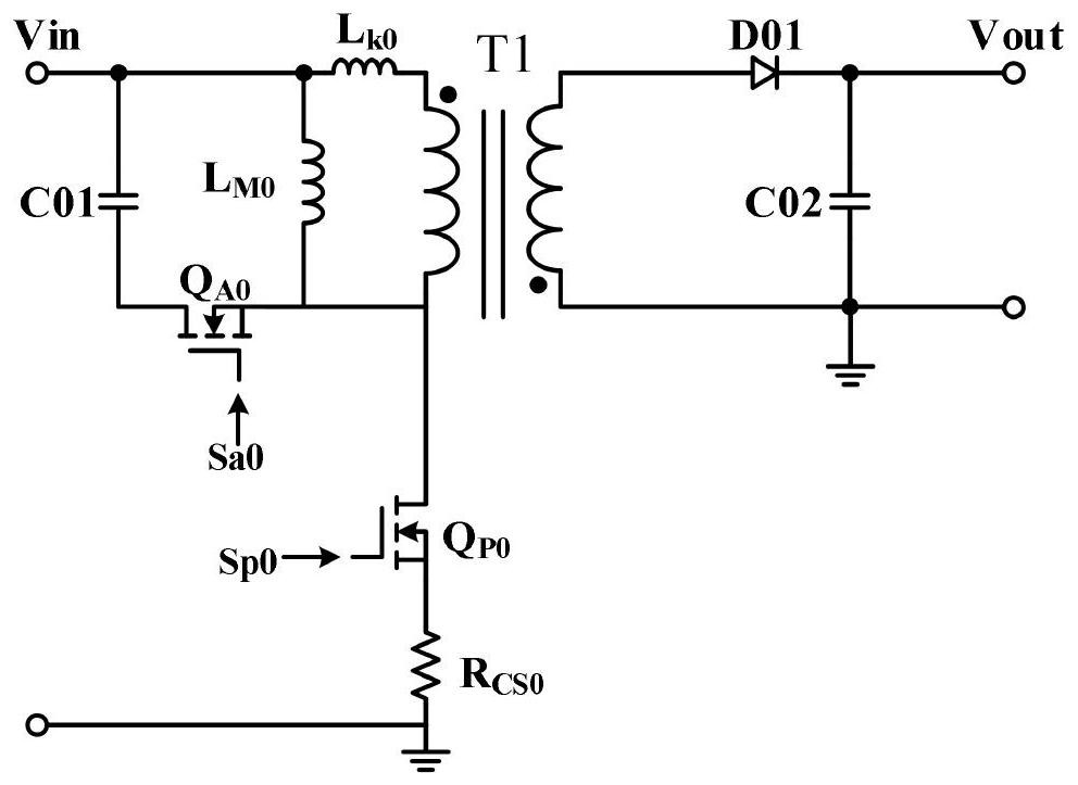
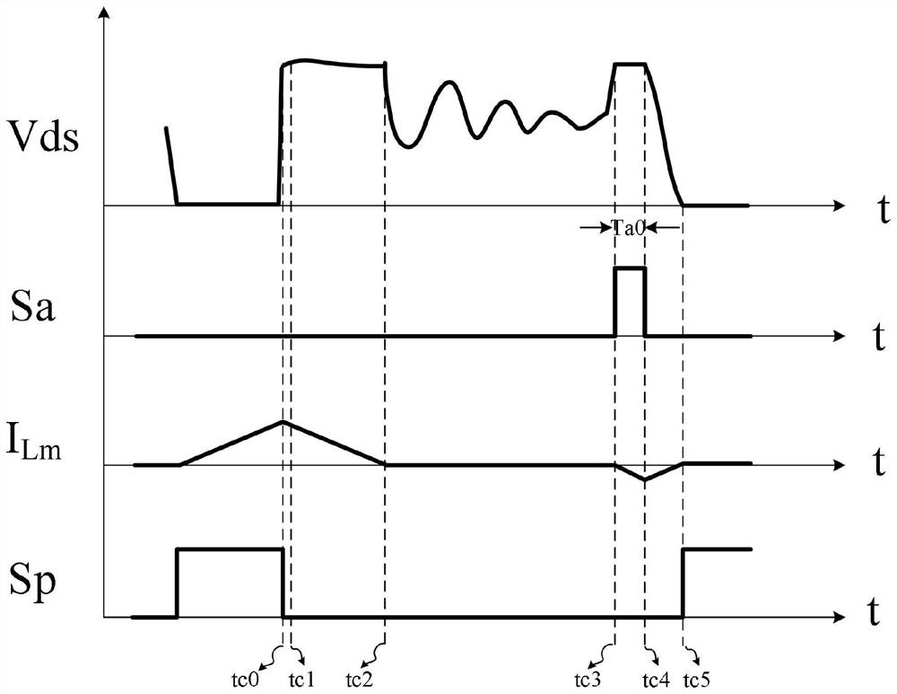
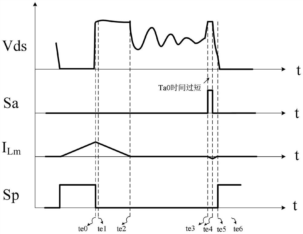
[0033] see Figure 1-13 , the present invention provides a technical solution: a clamp tube light-load conduction control method in an active clamp flyback topology, including an active clamp flyback circuit, and also includes a light-load conduction control circuit, a light-load conduction control The conduction control circuit is connected with the active clamp flyback circuit, and the light-load conduction control circuit includes a detection circuit, a first conduction time control module, a second conduction time control module and a drive unit, and the detection circuit and the drive unit are both Connected with an active clamp flyback circuit, the control method specifically includes the following steps:

[0034] Step 1: The detection circ...


PUM


Abstract

The invention relates to the technical field of active clamping flyback control, and discloses a clamping tube light-load conduction control method in active clamping flyback topology, which comprises an active clamping flyback circuit and a light-load conduction control circuit, and is characterized in that the light-load conduction control circuit is connected with the active clamping flyback circuit; the light-load conduction control circuit comprises a detection circuit, a first conduction time control module, a second conduction time control module and a driving unit. The detection circuit and the driving unit are connected with the active clamping flyback circuit. According to the invention, the clamping tube is controlled to be conducted twice in one period, a certain degree of negative current is generated in the two times, and proper conduction time is searched for in the first time, so that the second conduction duration is determined to be relatively accurate, and the problem that the conduction time of the clamping tube is too short or too long is effectively avoided; the circuit is used for accurately realizing zero-voltage conduction under light load, and effectively reducing the conduction loss.

Description

technical field [0001] The invention relates to the technical field of active clamp flyback control, in particular to a light-load conduction control method and circuit of a clamp tube in an active clamp flyback topology. Background technique [0002] The active clamp flyback (ACF) can realize the recovery of leakage inductance energy and realize the zero voltage conduction (ZVS) of the primary power device, thereby effectively improving the system efficiency and reducing the conduction loss. active clamp flyback topologies such as figure 1 LM and Lk represent the equivalent excitation inductance and leakage inductance of the transformer respectively, C01 is the clamp capacitor, QP0 and QA0 are the main power tube and clamp tube respectively, Sp0 and Sa0 are the control signals of the two, through QP0 The alternate conduction of QA0 and QA0 can realize the zero-voltage turn-on of the main power transistor of the primary side. [0003] see figure 2 , an ideal working wave...

Claims


Application Information

Patent Timeline
Patent Type & Authority Applications(China)
IPC IPC(8): H02M3/335H02M1/088H02M1/38
CPCH02M3/33569H02M1/088H02M1/38
Inventor 鲁扬李海龙欧阳金星
Owner NANJING MICRO ONE ELECTRONICS
Why Eureka
Try Eureka