
Sewage tank and scrubber

A sewage tank and tank technology, applied in manual floor scrubbing machines, carpet sweeping, cleaning machines, etc., can solve the problems of low gas-liquid-solid separation rate, high use cost, low use cost, etc., to ensure smoothness, Low cost of use and the effect of reducing the cost of filtration

Active Publication Date: 2022-03-18
GREE ELECTRIC APPLIANCES INC
View PDF8 Cites 0 Cited by
  • Summary
  • Abstract
  • Description
  • Claims
  • Application Information

AI Technical Summary

Problems solved by technology

[0004] Aiming at the problems of low gas-liquid-solid separation rate and high use cost of the existing sewage tank, this application proposes a sewage tank and a floor scrubber. And the washing machine has the technical effect of high separation rate and low use cost

Method used


Image

  • Sewage tank and scrubber
  • Sewage tank and scrubber
  • Sewage tank and scrubber

Examples


Embodiment Construction

[0045] In order to make the above-mentioned purpose, features and advantages of the present application more obvious and understandable, the specific implementation manners of the present application will be described in detail below in conjunction with the accompanying drawings. In the following description, numerous specific details are set forth in order to provide a thorough understanding of the application. However, the present application can be implemented in many other ways different from those described here, and those skilled in the art can make similar improvements without departing from the connotation of the present application, so the present application is not limited by the specific embodiments disclosed below.

[0046] In the description of the present application, it should be understood that the terms "center", "longitudinal", "transverse", "length", "width", "thickness", "upper", "lower", "front", " Back", "Left", "Right", "Vertical", "Horizontal", "Top", "...


PUM


Abstract

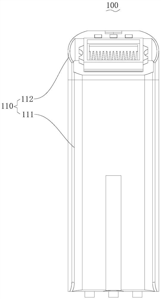
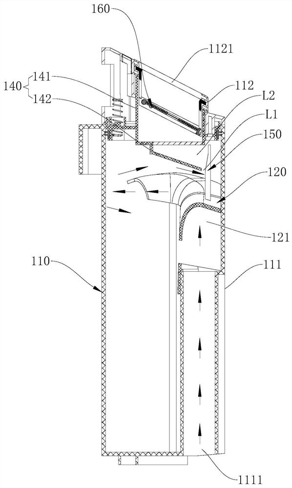
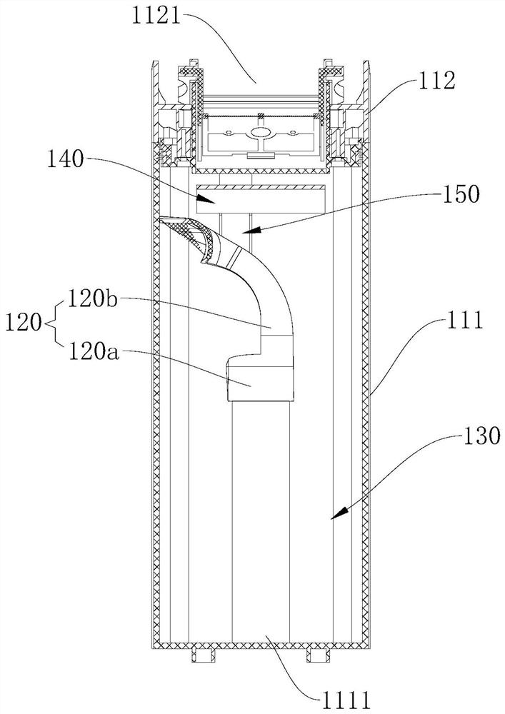
The invention relates to a sewage tank and a scrubber. The sewage tank comprises a tank body and a volute part. The box body is provided with an air outlet and an air inlet which are communicated with the inside and the outside of the box body, and the air outlet is located above the air inlet in the gravity direction. The volute part is arranged in the box body and spirally extends upwards along the side wall of the box body to form a spiral drainage channel, the volute part is connected with the air inlet, and the spiral drainage channel is communicated with the air inlet and the interior of the box body and used for guiding fluid flowing out of the spiral drainage channel to have a speed component horizontally tangent to the side wall of the box body. The side, away from the air outlet, of the volute part is provided with an opening communicating with the spiral drainage channel and the interior of the box body. According to the device, the separation path of airflow and solid-liquid garbage is prolonged, the separation efficiency is improved, the filtering cost is reduced, the use cost of a user is low, and cleaning is convenient for the user.

Description

technical field [0001] The present application relates to the technical field of cleaning equipment, in particular to a sewage tank and a floor washing machine. Background technique [0002] As a star product in the cleaning category, the floor washing machine innovatively combines the vacuum cleaner and the mop to realize the integration of suction and mopping, and can handle dry and wet garbage at the same time, and realizes the hands-free cleaning of the mop, which can free your hands and easily complete the task of mopping the floor. More and more consumers favor. [0003] The sewage tank structure is an important part of the washing machine, and its main function is to collect, separate and store dry and wet garbage. Its working process is that the fan draws air from the tuyere to form a negative pressure, and the sewage and solid waste are sucked into the sewage tank through the pipe. The existing sewage tank structure mainly realizes the separation of gas-liquid and...

Claims


Application Information

Patent Timeline
Patent Type & Authority Applications(China)
IPC IPC(8): A47L11/40A47L11/30
CPCA47L11/4016A47L11/4027A47L11/30A47L2201/00Y02W10/10
Inventor 覃德华康津李磊
Owner GREE ELECTRIC APPLIANCES INC
Learn More